The APWACurbs subassembly inserts links for a standard shape concrete kerb-and-channel with subbase. The kerb and channel dimensions are based on the APWA Standard Plans for Public Works Construction, 2012 edition.
You should verify that the dimensions used match your interpretation of the standard plan.
APWA Kerbs A1-6 and A1-8
APWA Kerbs A3-6 and A3-8
APWA Kerbs B1-6
APWA Kerbs B2-6
APWA Kerbs B3-6
APWA Kerbs C1-6 and C1-8
APWA Kerbs C2-6
APWA Kerbs D1-6 and D1-8
APWA Kerbs A2-6 and A2-8
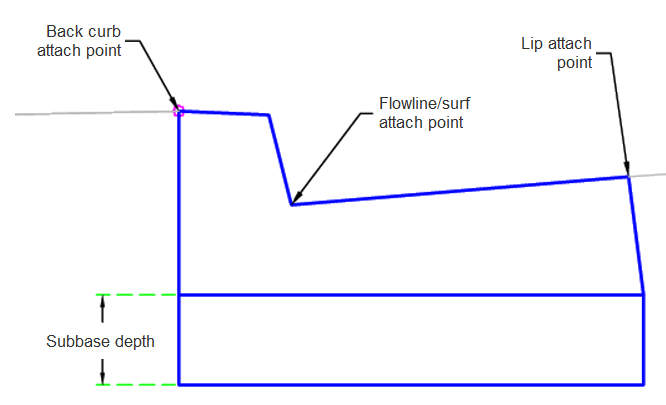
Attachment
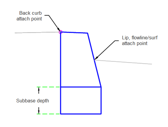
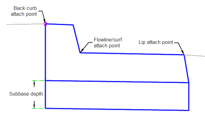
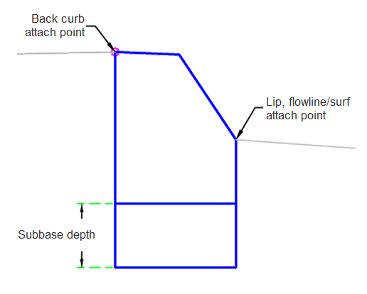
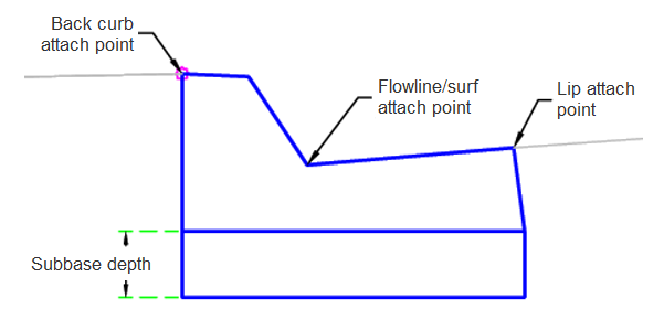
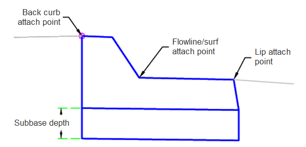
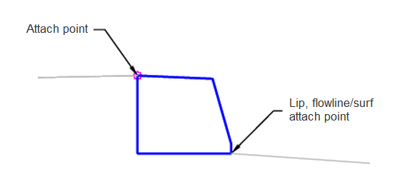
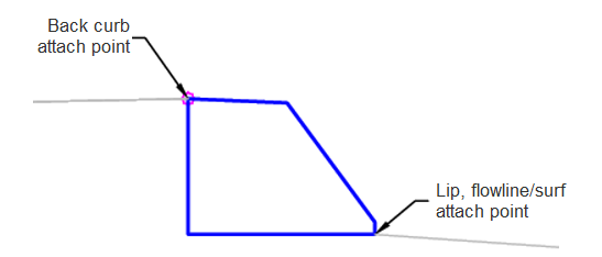
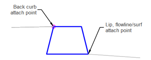
The attachment point is at the flange point of the channel, the back of the kerb or the face of the kerb.
Input Parameters
|
Parameter |
Description |
Type |
Default |
|---|---|---|---|
|
Side |
Specifies to insert the subassembly either on the right or the left side of the attachment point. |
Left / Right |
Right |
| Kerb Type | Specifies the kerb to be used. | A1-6 / A1-8 / A2-6 / A2-8 / A3-6 / A3-8 / D1-6 / D1-8 / C1-6 / C1-8 / B1-6 / B2-6 / B3-6 / D2-6 / C2-6 | A1-6 |
| Attach Point | Specifies where the kerb attach point is. | Lip/ BackKerb / Flowline-Surface |
10.0 ft 3.0 m |
| Subbase Depth | Depth to subbase at the flange point. Use zero if there is no subbase. | Numeric, Positive |
0.5 ft 0.150 m |
Target Parameters
This section lists the parameters in this subassembly that can be mapped to one or more target objects. For more information, see To Specify Corridor Targets.
None.
Runtime Logical Assignments
None.
Output Parameters
None.
Behavior
The kerb and channel links are inserted based on the values stored within the subassembly. All dimensions are positive, non-zero values. If a non-zero subbase depth is given, the subbase layer is not inserted. The subbase layer closes to the bottom-back-of-kerb.
The subassembly builds the shape for the selected kerb, kerb and channel, or surface kerb, with the attachment point either at (a) inside edge of the channel (or lip), or (b) the back of the kerb or (c) the flowline (or surface) of the kerb or channel.
Layout Mode Operation
In layout mode, this subassembly displays the kerb-and-channel component based on the input parameters given.
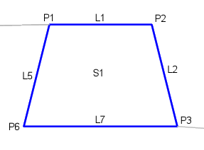
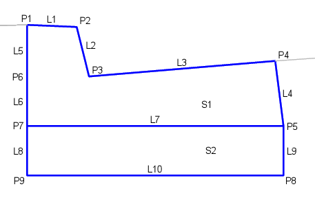
Point, Link and Shape Codes
The following table lists the point, link and shape codes for this subassembly that have codes assigned to them. Point, link or shape codes for this subassembly that do not have codes assigned are not included in this table.
|
Point, Link or Shape |
Code |
Description |
|---|---|---|
| P1 | BackKerb | Back-of-kerb |
| P2 | TopKerb | Top-of-kerb |
| P3 | InvertLevel_Channel | Channel flowline point or Finish Surface |
| P4 | Flange | Flange point of the channel |
| L1 - L3 | Top, Kerb | Finish surface on the kerb and channel |
| L4 - L6 | Kerb | |
| L7 | KerbBottom, Datum | |
| L10 | SubBase, Datum | |
| S1 | Kerb | Kerb-and-channel concrete area |
| S2 | SubBase |
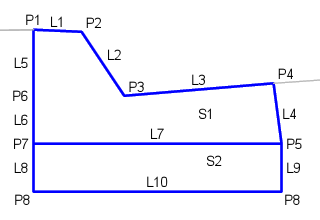
Coding Diagram
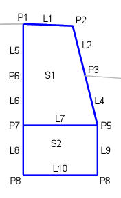
APWA Kerbs A1-6 and A1-8
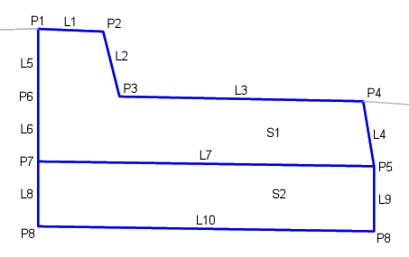
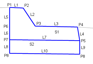
APWA Kerbs A3-6 and A3-8
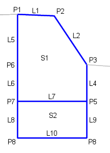
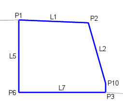
APWA Kerbs B1-6
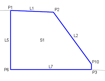
APWA Kerbs B2-6
APWA Kerb B3-6
APWA Kerbs C1-6 and C1-8
APWA Kerb C2-6
APWA Kerbs D1-6 and D1-8
APWA Kerbs A2-6 and A2-8