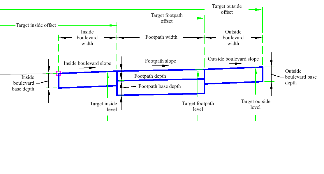
The FootpathSlopesAndBase subassembly creates links for a concrete footpath with inside and outside boulevards.
Attachment
The attachment point is at the inside edge of the inside boulevard. The FootpathSlopesAndBase subassembly is typically attached to a back-of-kerb or edge of pavement.
Input Parameters
|
Parameter |
Description |
Type |
Default |
|---|---|---|---|
| Side | Specifies which side to place the subassembly. | Left/Right | Right |
| Inside Boulevard Width | Width of the inside grass boulevard. | Numeric, positive |
4 ft 1.2 m |
| Outside Boulevard Slope | Width of the outside grass boulevard. | Numeric, positive |
0.5 ft 0.15 m |
| Footpath Base Depth | Depth to subbase below the footpath. Use zero if there is no subbase. | Numeric, positive |
0.5 ft 0.15 m |
| Inside Boulevard Base Depth | Depth of base of the inside grass boulevard. | Numeric, positive |
0.5 ft 0.15 m |
| Footpath Depth | Depth of the footpath. | Numeric, positive |
0.333 ft 0.10 m |
| Outside Boulevard Slope | % slope of the outside boulevard. | Numeric | 4 (%) |
| Footpath Slope | % slope of the footpath. | Numeric | 2 ( % ) |
| Inside Boulevard Slope | % slope of the inside boulevard. | Numeric | 4 (%) |
| Outside Boulevard Width | Width of the outside boulevard. | Numeric, positive |
2 ft 0.6 m |
| Footpath Width | Width of the footpath. | Numeric, positive |
5 ft 1.5 m |
Target Parameters
This section lists the parameters in this subassembly that can be mapped to one or more target objects. For more information, see To Specify Corridor Targets.
|
Parameter |
Description |
Status |
|---|---|---|
| Inside Boulevard Width | May be used to override the fixed Inside Boulevard Width and tie the inside edge-of-footpath to an offset alignment. The following object types can be used as targets for specifying this offset: alignments, polylines, features lines, or survey figures. | Optional |
| Outside Boulevard Level | May be used to override the outside boulevard slope and tie the outer edge of the outside boulevard to the level of a profile. The following object types can be used as targets for specifying the level: profiles, 3D polylines, feature lines, or survey figures. | Optional |
| Outside Boulevard Width | May be used to override the fixed Outside Boulevard Width with an offset alignment. The following object types can be used as targets for specifying this offset: alignments, polylines, features lines, or survey figures. | Optional |
| Footpath Level | May be used to override the footpath slope and tie the outer edge of the footpath to the level of a profile. The following object types can be used as targets for specifying the level: profiles, 3D polylines, feature lines, or survey figures. | Optional |
| Footpath Width | May be used to override the fixed Width of Footpath and tie the outside edge-of-footpath to an offset alignment. The following object types can be used as targets for specifying this offset: alignments, polylines, features lines, or survey figures. | Optional |
| Inside Boulevard Level | May be used to override the inside boulevard slope and tie the outer edge of the inside boulevard to the level of a profile. The following object types can be used as targets for specifying the level: profiles, 3D polylines, feature lines, or survey figures. | Optional |
Runtime Logical Assignments
None.
Output Parameters
None.
Behavior
The inside grass strip, footpath, and outside grass boulevard links are inserted outward from the attachment point at the given slope. The grass strips can be omitted by specifying a zero-width.
Optionally, various element widths can be attained by attaching to offset alignments. Also, the cross slopes can be derived by tying into offset profiles.
Layout Mode Operation
In layout mode the subassembly displays the links comprising the boulevards, footpath, and base.
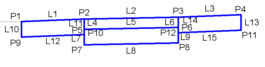
Point, Link, and Shape Codes
The following table lists the point, link, and shape codes for this subassembly that have codes assigned to them. Point, link, or shape codes for this subassembly that do not have codes assigned are not included in this table.
|
Point, Link, or Shape |
Code |
Description |
|---|---|---|
| P1 | Top | |
| P2 | Footpath_In, Top | Inside Footpath |
| P3 | Footpath_Out, Top | Outside Footpath |
| P4 | OutsidePointCode, Top | Outside Point Code |
| P5 | Footpath_Datum, BottomConcrete | Footpath Datum, Bottom of Concrete |
| P6 | Footpath, BottomConcrete | Bottom of Concrete |
| P7, P8 | Footpath_Base | Footpath Base |
| P9, P10 | InsideBaseDepth | Inside Base Depth |
| P11, P12 | OutsideBaseDepth | Outside Base Depth |
| L1 | Top | |
| L2 | Top, Footpath | |
| L3 | Top | |
| L5, L6 | Footpath, Datum | |
| L7 | Footpath | |
| L8, L10, L13, L14 | Base, Datum | |
| L9 | Footpath_Base | Footpath Base |
| L11 | InsideBaseDepth | Inside Base Depth |
| L12 | InsideBase, Datum | Inside Base |
| L15 | OutsideBaseWidth | Outside Base Width |
| S1 | Footpath | |
| S2, S3 | BasePlanter | Base Planter |
| S4 | Base |
Coding Diagram