The CrossChannel subassembly inserts links to create cross channel placed at an intersection.
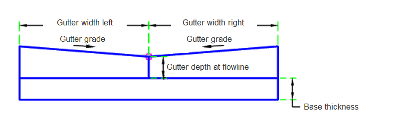
Case 1: Both
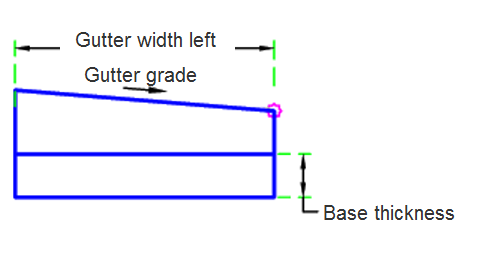
Case 2: Left
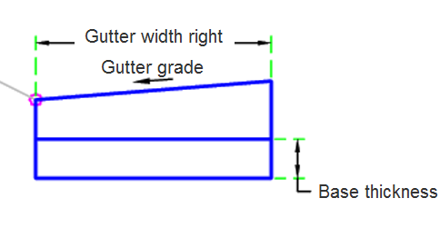
Case 3: Right
Attachment
The attachment point is at flowline of the cross channel. This component can be attached to either the left or right side.
Input Parameters
|
Parameter |
Description |
Type |
Default |
|---|---|---|---|
| Side | Specifies which side to place the subassembly. | Left / Right | Right |
| Channel Composition | Determines if the left, right, or both are built | Both / Left / Right | Both |
| Base Thickness | Thickness of base under channel | Numeric, positive |
0.5 ft 0.15 m |
| Channel Depth At Flowline | Depth of channel at the flowline | Numeric, positive |
0.5 ft 0.15 m |
| Channel Gradient | Channel gradient | Numeric | 8 (%) |
| Channel Width Left | Channel width left | Numeric, positive |
3 ft 0.9 m |
| Channel Width Right | Channel width right | Numeric |
3 ft 0.9 m |
Target Parameters
This section lists the parameters in this subassembly that can be mapped to one or more target objects. For more information, see To Specify Corridor Targets.
|
Parameter |
Description |
Status |
|---|---|---|
| Edge Level Right | May be used to override the right edge level of the cross channel. The following object types can be used as targets for specifying the level: profiles, 3D polylines, feature lines, or survey figures. | Optional |
| Edge Level Left | May be used to override the left. The following object types can be used as targets for specifying the level: profiles, 3D polylines, feature lines or survey figures. | Optional |
| Edge Offset Left | May be used to override the left edge level of the cross channel. The following object types can be used as targets for specifying this offset: alignments, polylines, features lines or survey figures. | Optional |
| Edge Offset Right | May be used to override the right width of the cross channel. The following object types can be used as targets for specifying this offset: alignments, polylines, features lines or survey figures. | Optional |
Runtime Logical Assignments
None.
Output Parameters
None.
Behavior
The channel links are inserted based on the input parameters. The targets may override the outside edge of the cross channel on both the right and left sides. If the base thickness is greater than 0, then the base is built under the cross channel.
Layout Mode Operation
In layout mode, this subassembly displays the cross channel components based on the input parameters given.
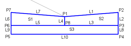
Point, Link and Shape Codes
The following table lists the point, link and shape codes for this subassembly that have codes assigned to them. Point, link or shape codes for this subassembly that do not have codes assigned are not included in this table.
|
Point, Link or Shape |
Code |
Description |
|---|---|---|
| P1 | FL | Flowline |
| P2, P7 | ChannelEdge | Edge of the channel |
| P3, P6 | Edge_Datum | Cross Channel Edge bottom |
| P4, P5 | Base_Datum | Bottom of the base |
| P8 | FL_Datum | Datum at the flowline |
| L1, L7 | Top, Channel | Top of the cross channel |
| L3, L5 | Channel, Datum | Bottom of the channel |
| L10 | Base, Datum | Bottom of the base |
| S1, S2 | Channel | Channel concrete |
| S3 | Base | Base |
Coding Diagram