The ClarkCountyRainGardenV subassembly inserts links to create a Clark County Rain Garden V, adjacent to the kerb.
You should verify the dimensions used match your interpretation of the standard plan.
Attachment
The attachment point is at the inside edge of the inside slope. This component can be attached to either the left or right side.
Input Parameters
|
Parameter |
Description |
Type |
Default |
|---|---|---|---|
| Side | Specifies which side to place the subassembly. | Left / Right | Right |
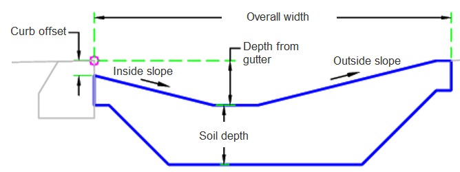
| Overall Width | Overall width of rain garden | Numeric, positive |
12.0 ft 3.6 m |
| Depth From Channel | Depth from the adjacent attach point. | Numeric |
-1.0 ft 0.3 m |
| Soil Depth | Depth of soil | Numeric, positive |
2 ft 0.6 m |
| Kerb Offset | Offset from the attachment point | Numeric |
-0.5 ft 0.15 m |
| Inside Sideslope | Inside sideslope | Slope | -4 ( : 1) |
| Outside Sideslope | Outside sideslope | Slope | -4 ( : 1) |
Target Parameters
This section lists the parameters in this subassembly that can be mapped to one or more target objects. For more information, see To Specify Corridor Targets.
None.
Runtime Logical Assignments
None.
Output Parameters
None.
Behavior
The initial point is set at the attachment point. The rain garden in then adjusted the entered offset distance. The depth of the rain garden is set from the input values.
Layout Mode Operation
In layout mode, this subassembly draws the rain garden in accordance with the input parameters.
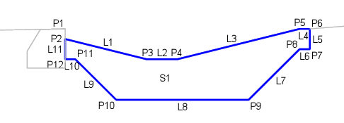
Point, Link and Shape Codes
The following table lists the point, link and shape codes for this subassembly that have codes assigned to them. Point, link or shape codes for this subassembly that do not have codes assigned are not included in this table.
|
Point, Link or Shape |
Code |
Description |
|---|---|---|
| P1 | RG_Gutter | Rain garden insertion point |
| P2 | RG_Top_In | Rain garden top inside |
| P3 | RG_Top_Out | Rain garden top outside |
| P6 | RG_Btm_Out | Rain garden bottom outside |
| P7 | RG_Btm_In | Rain garden bottom inside |
| L1 - L3 | Top, RG_Slope | Top of rain garden slope |
| L5-L7 | Datum | Datum |
| L6 | Datum, RG_Btm | Rain garden bottom |
| S1 | RainGarden | Rain garden |
Coding Diagram