The KerbEmbPipe subassembly inserts links for a concrete kerb with embedded pipe at the invert level. A terrace may be placed behind the kerb and channel.
Attachment
The attachment point is at the flange point of the channel.
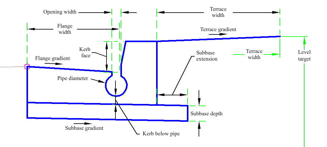
Input Parameters
|
Parameter |
Description |
Type |
Default |
|---|---|---|---|
|
Side |
Specifies to insert the subassembly either on the right or the left side of the attachment point. | Left/Right |
Right |
|
Flange Width |
Width from the flange of the channel to the invert level. | Numeric, positive |
1.5 ft 0.5 m |
|
Flange Gradient |
% slope of the channel. | Numeric |
6 (%) |
|
Subbase Extension |
Width that the subbase layer extends beyond the kerb. | Numeric |
0.5 ft 0.150 m |
|
Kerb Face |
Height from the invert level to the top of kerb. | Numeric |
0.5 ft 0.150 m |
|
Kerb below pipe |
Depth from the bottom of the pipe to the bottom of kerb below the invert of the pipe. | Numeric, positive |
0.25 ft 0.08m |
|
Subbase Depth |
Depth of the subbase layer at the attachment point (zero to omit). | Numeric, non-negative |
0.25 ft 0.08m |
|
Subbase Gradient |
% slope of the subbase. | Numeric |
2 (%) |
|
Pipe Diameter |
Drain pipe diameter. | Numeric, positive |
0.33 ft 0.1 m |
|
Opening Width |
Opening width of the pipe. | Numeric, positive |
0.25 ft 0.08m |
|
Terrace Width |
Width of the terrace. | Numeric, positive |
4 ft 1.2 m |
|
Terrace Gradient |
% slope of the terrace. Positive slopes are upwards from the attachment point. | Numeric |
4 (%) |
Target Parameters
This section lists the parameters in this subassembly that can be mapped to one or more target objects. For more information, see To Specify Corridor Targets.
|
Parameter |
Description |
Status |
|---|---|---|
|
Terrace Width Target |
May be used to set the horizontal location of the terrace behind the kerb. | Optional |
|
Terrace Level Target |
May be used to set the vertical location of the terrace behind the kerb. | Optional |
Runtime Logical Assignments
None.
Output Parameters
None.
Behavior
The subassembly builds the shape for a simple kerb and channel with a pipe located below the invert level. A terrace may be placed behind the kerb and channel.
Layout Mode Operation
In layout mode the subassembly displays the kerb and channel and terrace.
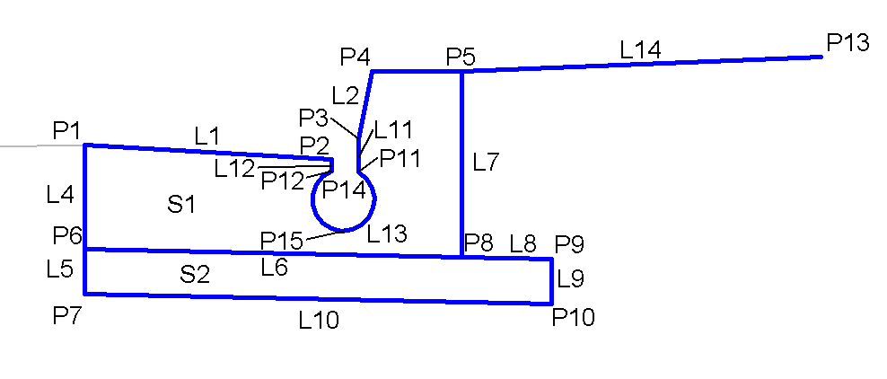
Point, Link, and Shape Codes
The following table lists the point, link, and shape codes for this subassembly that have codes assigned to them. Point, link, or shape codes for this subassembly that do not have codes assigned are not included in this table.
|
Point, Link, or Shape |
Code |
Description |
|---|---|---|
| P1 | Flange, Top | Flange of channel |
| P2 | InvertLevel_Channel, Top | Invert level of the channel |
| P3 | Top | |
| P4 | FaceKerb, Top | Top face of kerb |
| P5 | BackKerb, Top | Back of kerb |
| P6 | KerbDepth | Kerb Depth at Flange |
| P7 | SubbaseDepth | Base Depth below Flange |
| P8 | KerbBackBottom | Bottom point of kerb at back of kerb |
| P9 | SubbaseExtension | Top of Base Extension |
| P10 | SubbaseDepth, Datum | Bottom of Base Extension |
| P11 - P12 | Pipe | Top of the pipe at invert level |
| P13 | CG_Terrace, Top | End of Terrace |
| P14 | PipeCentre | Center of Pipe |
| P15 | Pipe_Invert | Invert of Pipe |
| L1 | Top, Flange, Kerb | Flange kerb link on finish gradient |
| L2 | Top, Kerb, KerbFace | Kerb face link on finish gradient |
| L3 | Top, Kerb, TopKerb | Top of kerb links on finish gradient |
| L4 | KerbDepth | Depth of kerb at attachment point |
| L5 | SubbaseDepth | Depth of base below the attachment point |
| L6 | Datum | |
| L7 | Kerb Height | Kerb height link on finish gradient |
| L8 | SubbaseExtension | Subbase extension behind the kerb |
| L9 | SubbaseDepth, Datum | Depth of the subbase |
| L10 | Datum, Subbase, KerbSub | Bottom of subbase |
| L11 - L12 | PipeEntrance | From the invert level to the top of the pipe opening |
| L13 | Pipe | Shape of pipe |
| L14 | Top, Terrace | Top of Terrace |
| S1 | Kerb | |
| S2 | Subbase |
Coding Diagram