The Driveway subassembly inserts links to create a driveway with a detached footpath. The driveway and kerb and channel is based on APWA Standard Plans for Public Works Construction, 2012 edition.
You should verify that the dimensions used match your interpretation of the standard plan.
Full Kerb:
Min Kerb:
Plan:
Attachment
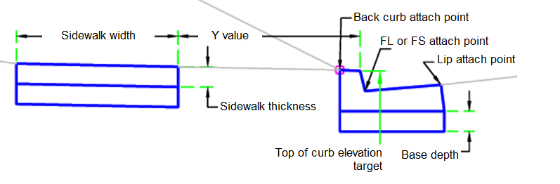
The attachment point is at the lip, back of kerb, or flowline/surface on the kerb and channel.
Input Parameters
|
Parameter |
Description |
Type |
Default |
|---|---|---|---|
| Side | Specifies which side to place the subassembly. | Left / Right | Right |
| Kerb Type | Specifies the kerb to be used | A1-6 / A1-8 / A2-6 / A2-8 / A3-6 / A3-8 / B1-6 / B2-6 / B3-6 | A2-6 |
| Attach Point | Specifies where the kerb attach point is | Lip / BackKerb / Flowline/Surface | Lip |
| Base Depth | Depth to subbase at the flange point. Use zero if there is no subbase. | Numeric, positive |
0.5 ft 0.15 m |
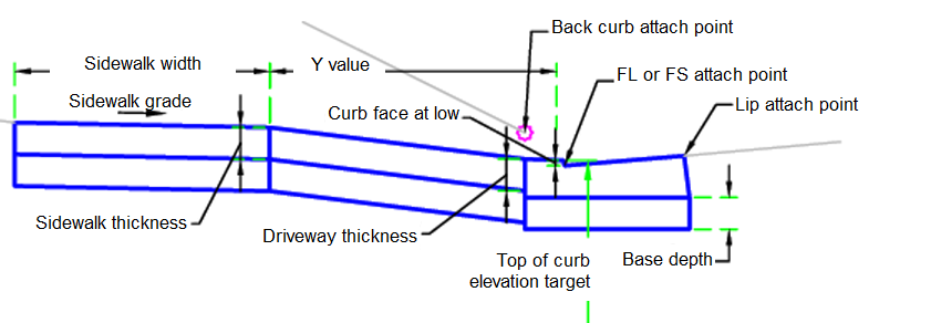
| Kerb Face at Low | Height of kerb face at the lowest point of the driveway | Numeric, positive |
0.083 ft 0.025 m |
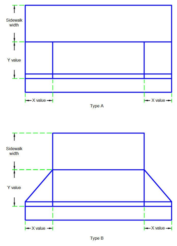
| Driveway Type | Type of driveway | Type A / Type B | Type B |
| Driveway Thickness | Thickness of driveway | Numeric, positive |
0.5 ft 0.15 m |
| Footpath Thickness | Thickness of footpath | Numeric, positive |
0.5 ft 0.15 m |
| Footpath Width | Width of footpath | Numeric, positive |
4 ft 1.2 m |
| Footpath Gradient | Gradient of footpath | Numeric | 2% |
| Y Value | Wing distance measured along the kerb | Numeric, positive |
4 ft 1.2 m |
| X Value | Width of driveway ramp | Numeric, positive |
3 ft 1 m |
Target Parameters
This section lists the parameters in this subassembly that can be mapped to one or more target objects. For more information, see To Specify Corridor Targets.
|
Parameter |
Description |
Status |
|---|---|---|
| Top of Kerb | Used to determine the driveway state to build the driveway. The following object types can be used as targets for specifying the level: profiles, 3D polylines, feature lines or survey figures. | Required |
Runtime Logical Assignments
The kerb and channel and driveway dimensions.
Output Parameters
None.
Behavior
The initial point is set at the attachment point. The kerb and channel shape is then built. The top of kerb is adjusted based on the top of kerb profile.
The type of driveway is determined by the user parameters. The top of kerb level target can not make the top of kerb higher than the kerb height, nor lower than the kerb face at the low location. A higher top of kerb level results in the maximum kerb height. A lower top of kerb level results in a level above the flowline/surface plus the kerb face at low input parameter.
For Type A:
The driveway is integral with the footpath for its entire length. The slope of the driveway is based on the full kerb height and the footpath gradient for a distance of the X value.
For Type B:
The driveway is not integral with the footpath for its entire length. For a distance Y, measured along the kerb, the driveway has a triangular wing shape. The distance for the driveway is based on the proportional kerb height and the X and Y input parameters.
Footpath:
The footpath location is built from the input parameters assuming a full kerb height along the driveway length.
Layout Mode Operation
In layout mode, this subassembly draws the full height kerb and footpath.
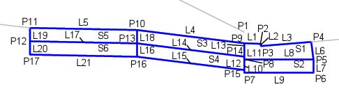
Point, Link and Shape Codes
The following table lists the point, link and shape codes for this subassembly that have codes assigned to them. Point, link or shape codes for this subassembly that do not have codes assigned are not included in this table.
|
Point, Link or Shape |
Code |
Description |
|---|---|---|
| P1 | BackKerb | Back of kerb |
| P2 | TopKerb | Top of kerb |
| P3 | FinishSurface | Finish surface or flowline |
| P4 | Flange | Channel flange |
| P10 | Driveway_Outside Footpath_Inside | Outside of driveway inside of footpath |
| P11 | Footpath_Outside | Outside of footpath |
| L1-L3, L6 | Top, Kerb | Top of kerb |
| L4 | Driveway, Top | Top of driveway |
| L5 | Footpath, Top | Top of footpath |
| L8 | KerbBottom, Datum | Bottom of kerb |
| L9, L15, L21 | SubBase, Datum | Bottom of subbase |
| L14 | Driveway_Sub | Bottom of driveway concrete |
| L17 | Footpath_Sub | Bottom of footpath |
| S1 | Kerb | Concrete kerb area |
| S2, S4, S6 | SubBase | Subbase |
| S3 | Driveway | Concrete driveway area |
| S5 | Footpath | Concrete footpath area |
Coding Diagram