The KerbAndChannelKerbRamp subassembly inserts links for a standard shape concrete kerb-and-channel with subbase that allows for adjustment of the kerb height by a profile to allow for the modelling of a kerb ramp. User-defined input parameters control the dimensions of the shape.
Attachment
The attachment point is at the flange point of the channel, the flowline or the back of the kerb.
Input Parameters
|
Parameter |
Description |
Type |
Default |
|---|---|---|---|
| Side | Specifies which side to place the subassembly. | Left / Right | Right |
| Insertion Point | Specifies insertion point of the kerb and channel as either Channel Edge, flowline or Back of Kerb | ChannelEdge / KerbBack / Flowline | Flowline |
| Channel Slope Method | Specifies method of channel slope input | OutsideLaneSlope / InsideLaneSlope / FixedSlope / UseDepth | FixedSlope |
| Channel Slope | Specifies fixed channel slope | Numeric | -2.00% |
| Channel Slope Direction | Specifies whether the channel slopes towards the crown or away from the crown | Away From Crown / Towards Crown | Away From Crown |
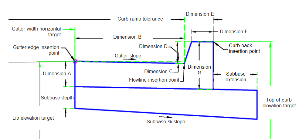
| Subbase Depth | Depth to subbase at the flange point. Use zero if there is no subbase. | Numeric, positive |
0.5 ft 0.15 m |
| Subbase Extension | Distance the subbase is extended beyond the back-of-kerb. Use zero to terminate the subbase at the back-of-kerb. | Numeric, positive |
1 ft 0.30 m |
| Subbase Slope Method | Specifies whether to use the Outside Lane superelevation slope for the subbase layer, or to set a numeric % slope value | Outside Lane Slope / Inside Lane Slope / Fixed Slope | Outside Lane Slope |
| Subbase %Slope | % slope of the subbase layer. Not used if Use SE is set to True. | Numeric, positive | 6% |
| Dimension A | Depth of the channel at the flange point | Numeric, positive, non-zero |
7 in 0.18 m |
| Dimension B | Width from the flange point to the channel invert level | Numeric, positive, non-zero |
30 in 0.75 m |
| Dimension C | Depth from the flange point to the channel invert level | Numeric, positive, non-zero |
1 in 0.025 m |
| Dimension D | Height of kerb from the channel invert level to the top-of-kerb | Numeric, positive, non-zero |
6 in 0.15 m |
| Dimension E | Width from the channel invert level to the back-of-kerb | Numeric, positive, non-zero |
8 in 0.20 m |
| Dimension F | Width of the top-of-kerb | Numeric, positive, non-zero |
6 in 0.15 m |
| Dimension G | Height of the back-of-kerb | Numeric, positive, non-zero |
13 in 0.33 m |
| Kerb Ramp Tolerance | Sets how far from the alignment the kerb ramp target may be considered found. Anything over the distance is considered not found. | Numeric, positive |
75 ft 22 m |
Target Parameters
This section lists the parameters in this subassembly that can be mapped to one or more target objects. For more information, see To Specify Corridor Targets.
|
Parameter |
Description |
Status |
|---|---|---|
| Channel Width | May be used to override the channel width. The following object types can be used as targets for specifying the width: alignments, polylines, feature lines or survey figures. | Optional |
| Lip Level | May be used to override the channel slope and tie the level of the kerb lip to the level of a profile. The following object types can be used as targets for specifying the level: profiles, 3D polylines, feature lines or survey figures. | Optional |
| Top Of Kerb Target | May be used to override the top of kerb level and tie the level of the top of kerb to the level of a profile. The following object types can be used as targets for specifying the level: profiles, 3D polylines, feature lines or survey figures. | Optional |
Runtime Logical Assignments
None.
Output Parameters
None.
Behavior
The kerb and channel links are inserted based on the Input Parameter dimensions Dimension A – Dimension F. All dimensions must be positive, non-zero values. If a non-zero subbase depth is given, the subbase layer is inserted to the back of kerb, and continues for the Subbase Extension width. The subbase layer closes to the bottom-back-of-kerb, as shown in the diagram.
If the insertion point is other than back of kerb, then the kerb height is adjusted by the Top Of Kerb Target. The adjustment may not exceed the top of kerb height or reduce the kerb face below zero. If the top of kerb level is exceeded the full face of the kerb is built. If the top of kerb level is less than zero, then a zero value is used.
If the insertion point is other than GutterEdge then the channel width and slope is adjusted if the targets for the channel edge are present. The channel slope and level targets may need to be non-standard to meet accessibility requirements.
The subassembly builds the shape for a kerb and channel, with the attachment point either at (a) inside edge of the channel (or lip), or (b) the back of the kerb, or (c) the flowline. The face of the kerb is given a small, constant width to make it non-vertical.
Layout Mode Operation
In layout mode, this subassembly displays the kerb-and-channel component based on the input parameters given.
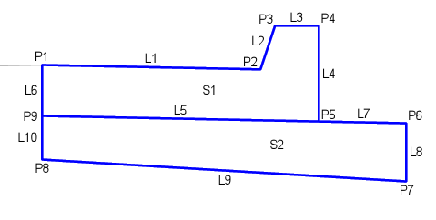
Point, Link and Shape Codes
The following table lists the point, link and shape codes for this subassembly that have codes assigned to them. Point, link or shape codes for this subassembly that do not have codes assigned are not included in this table.
|
Point, Link or Shape |
Code |
Description |
|---|---|---|
| P1 | Flange | Flange point of the channel |
| P2 | InvertLevel_Channel | Channel invert level point |
| P3 | TopKerb | Top-of-kerb |
| P4 | BackKerb | Back-of-kerb |
| L1 - L3 | Top, Kerb | Finish surface on the kerb and channel |
| L9 | SubBase, Datum | |
| S1 | Kerb | Kerb-and-channel concrete area |
| S2 | SubBase |
Coding Diagram