After you have edited envelope sub-objects for good overall mesh deformation, you can create bulges to simulate muscle contraction and expansion when a character’s joint rotates.
A bulge angle requires two links: the selected link, and the child link of that selection (for example, an upper arm and forearm). The joint that separates the two is referred to as the bulge joint. Any rotation applied to this joint becomes the angle used to center the effect of a bulge angle.
Physique creates a single default bulge angle for each bulge joint in the attached skeleton. The angle of this joint is that of the initial skeleton pose. This is the pose the skeleton had when the Physique modifier was applied to the skeleton, or when you use Reinitialize and turn on Initial Skeleton Pose in the Physique Initialization dialog. To create a bulge, you need to add only a single additional bulge angle. You can add further bulge angles to refine the bulge effect.
Workflow to Create a Biceps Bulge
The overall steps for creating a biceps bulge are:
- Insert a new bulge angle.
Give the new bulge angle a custom name and color.
- Set the bulge angle at a point where the joint is flexed; for example, at 90 degrees.
- Insert a cross section on the upper arm.
- Use control points (or the Bulge editor) to shape the bicep bulge.
The following paragraphs elaborate these steps.


Above: Default bulge angle at the initial pose.
.
Below: Bicep bulges at the custom bulge angle of 90 degrees.
The new bulge angle has been assigned a red color.
To create a biceps bulge angle, go to the Bulge sub-object level. In the Selection Level group, turn on Link. Select the upper arm link, then click Insert Bulge Angle; the bulge angle name increments from 0 to 1 in the Current Bulge Angle field, indicating that a new bulge angle has been created. Type a descriptive name for the new bulge angle in the Current Bulge Angle field; for example, Arm at 90.
Click Bulge Angle Color and select a color for the newly created bulge angle. When Select Nearest Bulge Angle is active, the bulge angle color changes as the joint bends; this is a good visual indicator of which angle has the most influence at any given frame.
Scrub the time slider to a frame where the arm is bent to 90 degrees, then click Set Bulge Angle (you can also rotate the joint).
In the Selection Level group, click Cross Section. Then in the Cross Section Parameters rollout, click Insert. In a viewport, position the cursor over the upper arm link, and click to place the new cross section for the biceps.
On the Selection Level rollout, click Control Point. To shape the cross section, move the cross section control points in the viewports, creating a bulge. Click Play. The biceps should grow as the angle of the character’s arm approaches 90 degrees. If Select Nearest Bulge Angle is active, the bulge angle gizmos change colors, depending on which angle has the greatest influence.
Go to the Link selection level and use Copy, Paste, and Mirror to create an identical bulge angle for the opposite arm.
Bulge Editor
The Bulge Editor duplicates many of the controls at the Bulge sub-object level. The benefit of using the Bulge Editor is that bulge angle data is represented graphically, and provides an alternative way of creating, selecting, and editing cross sections. Rather than editing cross section control points in the viewports to "bulge" the mesh, you might prefer to open the Bulge Editor and move control points in the Bulge Editor’s Cross Section view.
Procedures
To create a new bulge angle on a selected link:
- With the Bulge sub-object level active, click
 (Link) in the Selection Level group.
 - Select a link in a viewport.
- Click
 (Insert Bulge Angle).
 This creates a new bulge angle. The name in the Current Bulge Angle field increments.
Note: By default, one bulge angle is created by Physique in the initial skeletal pose; the arm is usually straight in this pose. - In the Current Bulge Angle field, enter a name, such as Arm at 90.
- Click the Bulge Angle Color swatch and choose a color in the color selector. This makes identification easier.
Now you need to set a joint angle for the newly created bulge angle.
- Drag the time slider until the joint is at the desired angle.
If the skeleton is not yet animated, you can exit the Bulge sub-object level,
 rotate the skeleton's joint until it is at the desired angle, then return to the Bulge sub-object level.
 - Click
 (Set Bulge Angle). The joint angle between the link and its child is recorded (for example, if a biped's upper arm link is selected, Set Bulge Angle records the angle created by the upper arm and the forearm.)
 - In the Selection Level group, click
 (Cross Section). Then in the Cross Section group, click Insert. In a viewport, click the link at the point where you want the new cross section to be.
 -
 Scale the cross section or move its control points to create the bulge.
 To move individual control points, use the
 (Control Point) selection level.
 - Enter 80.0 in the Influence field.
If the bulge angle is for a biceps bulge when the forearm and upper arm create a 90-degree angle, the bulge begins to appear at 10 degrees.
To copy all Bulge angles from one link to its opposite:
- Go to the Bulge sub-object level.
- In the Selection Level group, click
 (Link). In a viewport,
  select a link to copy.
 - Choose Entire Link from the Current Bulge Angle drop-down list.
- In the Cross Section Parameters rollout, click Copy.
- In a viewport,
 select the opposite link.
 - In the Cross Section Parameters rollout, click Paste, and then click Mirror.
All the bulge angles from the first link are pasted to the opposite link, then mirrored.
To choose a specific bulge angle for editing:
- Click the arrow of the Current Bulge Angle drop-down list.
The full list of bulge angle names appears for the current link.
- Click the name of the bulge angle you want to edit.
The viewports update to show the cross sections associated with the newly selected bulge angle.
To change a bulge angle value:
- Make sure the bulge angle's name is displayed in the Current Bulge Angle drop-down list.
- Drag the time slider to a frame that displays the angle you want to record, or use transforms to change the angle between the active link and its child link.
- In the Bulge Angle Parameters group, click
 (Set Bulge Angle).
To delete a bulge angle:
- Click the arrow of the Current Bulge Angle drop-down list.
The full list of bulge angle names is displayed.
- Click the name of the bulge angle you want to delete.
- Click
 (Delete Bulge Angle).
 You can’t delete the default bulge angle: a link must always have at least one bulge angle defined.
To use Select Nearest Bulge Angle:
- In the Selection Level group, click
 (Select Nearest Bulge Angle).
 - Scrub the time slider or
 rotate the joint.
 The bulge angle named in the drop-down list changes to show the most influential bulge at each skeleton pose.
The Select Nearest Bulge Angle button can help you identify the bulge angle that has the greatest effect at the current pose.
Interface
Controls for the Bulge sub-object level are on the Bulge rollout.

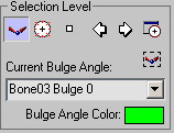
Selection Level group

-
 Link
Link - Turn on to select links in the viewports. The Copy, Paste, and Mirror commands are enabled for links.
-
 Cross Section
 - Turn on to select and edit cross sections in order to "bulge" the mesh. The Insert, Delete, Copy, Paste, and Mirror commands are enabled for cross sections.
-
 Control Point
 - Turn on to edit cross section control points.
-
 Previous and Next
 - Click to select the next or previous link, cross section, or control point, depending on the selection level.
-
 Bulge Editor
 - Click to display the Bulge Editor, which lets you create and edit bulge angles using the schematic Cross Section and Profile views
-
 Select Nearest Bulge Angle
 - Turn on to select the bulge angle nearest to the current joint angle. If a joint bends over time, this lets you use the time slider to select a bulge angle. If you click Play, you can see the Current Bulge Angle field change to reflect the nearest bulge angle to the current angle of the selected link and its child (if two or more bulge angles for the limb exist).
-
 Current Bulge Angle (field and drop-down list)
 - Displays the current bulge angle. You can enter a descriptive name for a newly created bulge angle. When you click Insert Bulge Angle, this field displays the new bulge angle name. Use the drop-down list to select other bulge angles.
- Entire Link
- This choice in the Current Bulge Angle drop-down list selects all cross sections for all bulge angles in the active link. Use this to change cross section settings globally for a link. This also affects the Copy and Paste commands. While Entire Link is chosen, Copy Cross Section copies all cross sections for all bulges, and Paste Cross Section pastes all cross sections for all bulges. Tip: Entire Link is useful for copying all the bulges from one arm or leg to another.
- Bulge Angle Color
- Click the color swatch to change the color of the current bulge angle. Giving each bulge angle a different color is a convenient way to distinguish between them.
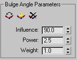
Bulge Angle Parameters group

-
 Set Bulge Angle
 - Changes the angle value to the skeleton’s current joint angle on the current bulge angle (visible in the Current Bulge Angle field in the Selection Level group). First use Move or Rotate in a viewport to change the angle between the selected link and its child, then click Set Bulge Angle.
-
 Insert Bulge Angle
 - Adds a new bulge angle for the selected link. The Current Bulge Angle field displays a bulge angle name with the number incremented. You can enter a descriptive name for a new bulge angle, such as Arm at 90.
By default, one Bulge Angle is created in the Figure mode pose when Physique creates links. Only one additional bulge angle is needed to bulge the mesh. You can create more bulge angles for further control, if you want.
-
 Delete Bulge Angle
 - Removes the current bulge angle from the selected link.
You cannot delete the default bulge angle.
- Influence
- The range of angles through which the bulge influences the skin. Range =0 to 180. Default=90 degrees.
For example, if you’ve set a bulge angle for the joint at 90 degrees, an Influence value of 40 means that the bulge effect begins to appear when the rotating joint reaches 50 degrees (90 minus 40) or 130 degrees (90 plus 40).
- Power
- Controls how smoothly or abruptly the bulge takes effect. At 0.0, the bulge takes effect immediately, without interpolated easing. As values increase, the bulge eases in gradually. A value of 10.0 will bulge the mesh abruptly when the set angle is reached. Range=0 to 10.0. Default=2.5.
- Weight
- Increases the effect of the current bulge angle relative to the effect of any other bulges. Range=0.0 to 100.0. Default=1.0.
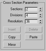
Cross Section Parameters group

- Sections
- Sets the number of cross sections for the selected link.
- Divisions
- Sets the number of control points around the cross section. By default, control points are evenly distributed around the circumference of the cross section.
- Resolution
- Sets the number of radial divisions around the cross section. Control points snap to the nearest resolution line. Note: The buttons that follow, Insert, Delete, Copy, Paste, and Mirror, work according to which level is active in the Selection Level group.
- Insert
- Creates a new cross section or control point.
- Delete
- Deletes the active cross section or control point.
- Copy
- Copies the active link (with its bulge angles) or cross section.
- Paste
- Pastes a link (with its bulge angles) or cross section.
To copy and paste all the bulge angles from one link, choose Entire Link from the Current Bulge Angle drop-down list, and then click Copy. Select the opposite link and click Paste. Click Mirror to mirror the pasted link parameters.
- Mirror
- Mirrors bulge angles and cross sections on bulge angles. If necessary, you can then use Select And Rotate to orient the bulge angles and cross sections.
Display group

- Interactive Redraw
- Turn on to deform the mesh in real time while you edit cross sections in the viewports. Turn off to update the mesh only when you release the mouse. Default=on. Tip: Turn off Interactive Redraw when working on a slow system, or with a dense mesh that takes a long time to compute.
- Initial Skeletal Pose
- When on, puts the mesh into its original pose; that is, the pose it was in when Physique was first applied. Default=off.
- Display Options
- Click to display the Bulge Angle Display Properties dialog, which lets you customize the viewport display of bulges.