![]()
Here, you can view, create, and edit relationships between objects. You can create hierarchies, assign controllers, materials, modifiers, or constraints.
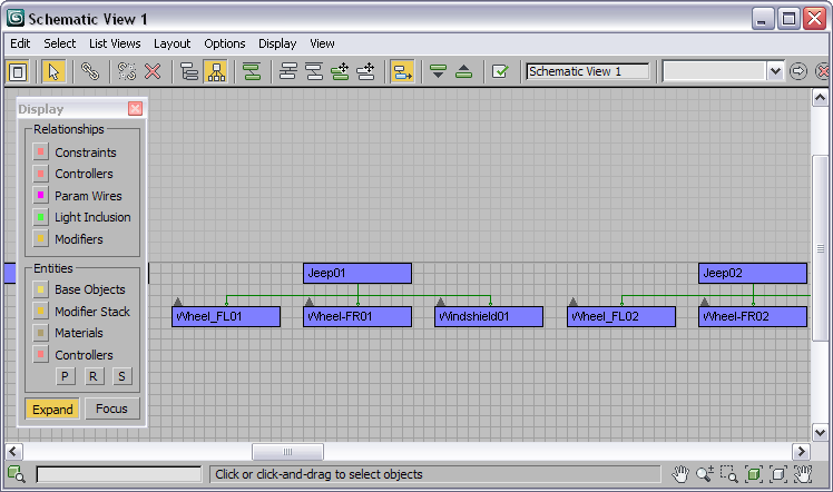
You can use the Schematic View Display floater to control what entities and relationships you want to see and work with. Use Schematic View to navigate complex hierarchies or scenes with large numbers of objects. Use Schematic View to understand and explore the structure of files you didn't create yourself.
One powerful feature is the list view. You can see the nodes in a text list which you can sort by criteria. The list views can be used to navigate extremely complex scenes quickly. You can use the relationship or instance viewer within Schematic View to see light inclusions or parameter wirings within the scene. You can control the display of instances or see a list of object occurrences.
Schematic View also allows for background image or grid, and automatic arrangement of nodes based on physical scene placement. This makes arranging nodes for character rigs easier.
Choose between a variety of arrangement selections so you can auto-arrange, or work in a free mode. The layout of the nodes is saved with the named Schematic View window. You can load a background image as a template for laying out the nodes in the window.
Schematic View Features
Here are some of the notable features of Schematic View:
- Layouts are saved with the named Schematic View file.
- Text remains readable during window navigation.
- Schematic View includes tools for displaying and arranging nodes including a free mode.
- You can use a background image or grid in the Schematic View window.
- You can see and edit wired parameters.
- A modeless display floater lets you turn on and off node display by category.
- The Relationship List Viewer enables quick navigation and selection of nodes. Relationships displayed includes Lights inclusion/exclusion, all parameter wires, constraints, controllers, and modifier relationships such as path deform paths and morph targets
- You can copy and instance controllers.
- You can assign controller types.
- Schematic View offers extensive MAXScript exposure.
- Ability to drill down to more properties (such as static values and custom attributes).
How the Components of Schematic View Behave
Everything displayed in the Schematic View window is shown as a box with a name. There are various conventions to indicate different states regarding these objects.
 Solid End
-
Signifies that the entity is arranged.
 Open end
-
Signifies that the entity is free.
 Red Border
-
Signifies that the entity is animated.
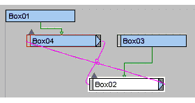
 End Arrow
-
Signifies that the entity shares a relationship with another entity.
 White Fill
-
Signifies that the entity is selected in the Schematic View window.
 White Border
-
Signifies that the entity is selected in the viewport.
 Up Arrow
-
Collapses the entity it springs from and all child entities thereof up into the parent entity
 Down Arrow
-
Expands the next child entity down from the entity that the arrow springs from.
 Overlap
-
Schematic View will prevent newly visible nodes from overlapping with existing nodes. This applies to free mode: make an object, free it, make another object and it will fall on top but to the right of the original object so both can be accessed and moved.
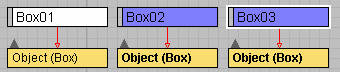
- Instances
-
Schematic View will bold the text of instanced entities, for nodes this will show up on the base object entity. In the example illustrated, Box02 and Box03 are instances.
Procedures
Interface
See the following topics describing the Schematic View user interface.