The PathDeform modifier deforms an object using a spline or NURBS curve as a path. You can move and stretch the object along the path, and rotate and twist it about the path. There is also a world-space version of this modifier, PathDeform (WSM).

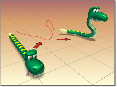
PathDeform shapes a snake.
Using a Path to Deform an Object
Use the object-space PathDeform modifier when you want to keep an object in place while deforming to a path. When you want to move an object to a path while keeping the path in the same world space, use the world-space PathDeform modifier instead.
To use the PathDeform modifier, click the Pick Path button immediately after applying it, and then select a shape or curve consisting of a single open or closed spline. Once the object is assigned to the path, you can adjust the parameters to deform or animate the object along a gizmo copy of the path.
Interface
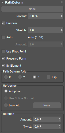
Path Deform rollout


- Pick Path button
- Click to select a spline or NURBS curve to use as the path. The gizmo that appears is shaped like the path and is aligned with the local Z axis of the object. Once you assign the path, you can adjust the deformation of the object using the remaining controls in this rollout. The path may contain multiple curves.
- Percent
- Sets the percentage along the spline path that will be used as the start of object deformation.
- Uniform
- Bases the percent calculation on the actual spline distance rather than interpolated between knots.
- Stretch
- Sets how much to stretch the source object along the path.
- Auto
- Uses the indicated value to stretch the source object across the entire spline length.
- Amount
- Sets the amount to stretch.
- Use Pivot Point
- Uses the pivot point of the object as the deformation reference point.
- Preserve Form
- When enabled, makes the object follow the spline while maintaining its shape rather than conform.
- By Element
- When enabled, deforms each mesh element on the model independently along the path. This option can help prevent a mesh with multiple elements from becoming deformed or distorted, for example when modeling tank treads.

By Element option enabled (right)
When enabled, the averaged center of the element is used to position the element on the path. When disabled, the pivot location of the mesh is used to position the object along the path.
Path Deform Axis group
- X
- Sets X as the deforming axis along the spline.
- Y
- Sets Y as the deforming axis along the spline.
- Z
- Sets Z as the deforming axis along the spline.
- Flip
- Reverses the gizmo path 180 degrees about the specified axis.
Up Vector group
- Adaptive
- Automatically calculates the up vector for the spline.
- Use Spline Normal
- Uses the spline normal as the up vector.
- Look At
- Sets the up vector to point at a selected object. To do this, click the button to the right and select an object from the scene.
Rotation group
- Amount
- Sets the amount of rotation constant along the length.
- Twist
- Twists the object about the path.
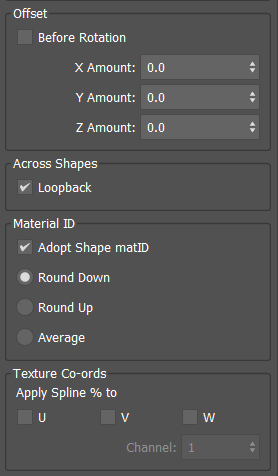
Offset group
- Before Rotation
- When enabled, applies the offset before performing rotation operations.
- X Amount
- Sets the offset value along the X axis.
- Y Amount
- Sets the offset value along the Y axis.
- Z Amount
- Sets the offset value along the X axis.
Across Shapes group
- Loopback
- When enabled, makes the deformed object loop back to the beginning of the spline. When disabled, the deformed object continues along the direction of the first or last knot.
Material ID group
- Adopt Shape matID
- Makes the object adopt the material ID(s) of the underlying spline(s).
- Round Down
- In the case of multiple splines, takes the lowest value.
- Round Up
- In the case of multiple splines, takes the highest value.
- Average
- In the case of multiple splines, takes the average value of the highest and lowest, rounding down.
Texture Coordinates group
- Apply Spline % to
- Allows the overwriting of UVW coordinates based on the percentage along the path of an object's vertex. Click to select the desired coordinates to be overwritten.
- Channel
- Specifies the target UVW channel.
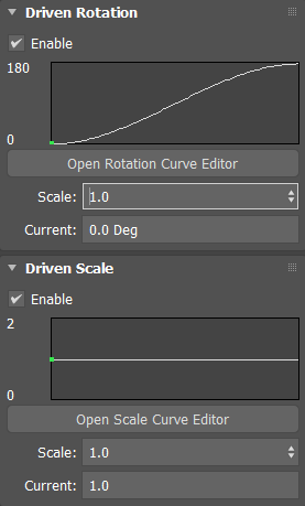
Driven Rotation and Scale rollouts
These features provide the ability to specify the rotation and scale of the deformed object along the spline's path.
The drawn curve represents the calculated value along the path of the driving spline. The 0% value will always equal 0 degrees of rotation/scale.

Driven Rotation rollout
- Enable
- Enables custom rotation along the spline.
- Open Rotation Curve Editor
- Opens the Rotation Curve editor where the curve can be edited using standard controls.
- Scale
- Multiplies all rotation values with the specified scale.
- Current
- Displays the current rotational angle for the deformed object along the spline. This field is not editable.
Driven Scale rollout
- Enable
- Enables custom scale along the spline.
- Open Scale Curve Editor
- Opens the Scale Curve editor where the curve can be edited using standard controls.
- Scale
- Multiplies all scale values.
- Current
- Displays the current scale for the deformed object along the spline. This field is not editable.
Procedures
To use the PathDeform modifier:
-
 Select an object.
- Apply PathDeform.
- On the Parameters rollout, click Pick Path.
- Click a spline or NURBS curve.
Deform the object by adjusting the various controls in the Path Deform panel and by editing the shape of the path object itself.
Example:
- In the Top viewport, create a circle with a radius of 100 units.
- In the Front viewport, create a text shape with six or seven letters, and a size of 50.
- Apply an Extrude modifier to the text shape and set Amount to –5.0.
- On the main toolbar, set the Reference Coordinate System to Local.
Looking at the axis tripod for the extruded text object, you can see that its Z axis runs from back to front, relative to world space.
- Apply a PathDeform object-space modifier to the text object, click the Pick Path button, and then select the circle.
3ds Max displays
a circular gizmo. The circle runs through the local Z axis of the text object. Because of its orientation, its effect is minimal, but you can see a slight wedge-shaped deformation from the top view.
- In the Path Deform Axis group, choose the Y option, and then the X option.
The circle gizmo rotates to run through the specified axes, deforming the text object differently with each change.
- Adjust the Percent spinner to view its effect, and then set it to 0. Try the same with Stretch.
Tip: Use the Ctrl key with Twist to amplify the effect.
- In the Path Deform Axis group, enable Flip to switch the direction of the path and disable it again.
- In the Rotation group, adjust Amount to see the effect of rotation, and adjust the Twist and Offset controls. Reset the values by right-clicking each option's spinners.
- In the stack display, choose the Gizmo sub-object level, and move the gizmo path around.
The text object is further deformed by its relative position to the gizmo.
- In the modifier stack, turn off sub-object selection by selecting the original circle shape.
- Adjust the circle's radius.
The deformation of the text object changes because its gizmo is an instance of the shape object.