Use the Chamfer modifier to procedurally add edges to specific parts of an object with an option for generating quadrilateral output. It can be applied at all sub-object levels and is typically used for rounding off edges, but can also be applied in situations where additional mesh resolution is required.

The Chamfer modifier provides an expanded feature set over chamfer functions built into objects such as editable poly. These features include driving curvature through crease weights, the ability to add insets, and a range of input and output options.
 Hard edges can appear on chamfer segments and cannot be corrected with the Smoothing parameter in the
Chamfer modifier. Starting in 3ds Max 2023.2, The
Chamfer modifier generates improved surface normals when working with non-explicit normals, solving this problem. You can use the command
$.modifiers[N].SetVersion #VerLatest to update
Chamfer modifiers that were applied in previous versions of 3ds Max, so they use this functionality.
Hard edges can appear on chamfer segments and cannot be corrected with the Smoothing parameter in the
Chamfer modifier. Starting in 3ds Max 2023.2, The
Chamfer modifier generates improved surface normals when working with non-explicit normals, solving this problem. You can use the command
$.modifiers[N].SetVersion #VerLatest to update
Chamfer modifiers that were applied in previous versions of 3ds Max, so they use this functionality.
Part 1: Create an object to chamfer:
- Create a Box primitive with the following parameters:
- Length: 60.0
- Width: 100.0
- Height: 12.0
- Length Segs: 3
- Width Segs: 3
- Height Segs: 1
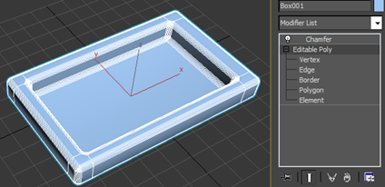
- Right-click and convert the box to an editable poly format.
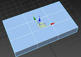
- In the modifier stack, click the + icon next to the Editable Poly entry to expand the sub-object hierarchy, then click the Edge item to activate the Edge sub-object level.
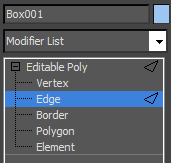
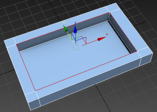
- Double-click an internal edge to select the loop and move it close to the outside of the box.
- Repeat this process for the three remaining inside-edge loops.
Tip: Press X and type Loop Tools to open a dialog where you can easily manipulate multiple selected loops using spinners.
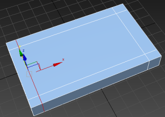
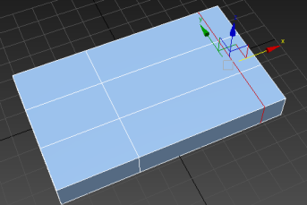
- Go to the Polygon sub-object level, select the inside polygon on the top of the box, and extrude it inward about 10 units. Exit Extrude mode.
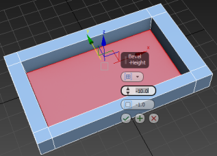 Note: 3ds Max provides various methods for achieving a result similar to this, but this one is particularly apt for examining the Chamfer modifier options.
To demonstrate the main Chamfer modifier features, let's create a simple tray-like object.
Part 2: Apply the Chamfer modifier and change settings:
- Go to the Edge sub-object level and select the four inner edges at the top of the box.
- From the Modifier List on the Modify panel, choose Object-Space Modifiers
 Chamfer.
This applies the Chamfer modifier to the object and opens the Chamfer rollout on the Modify panel where you can adjust the settings.
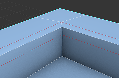
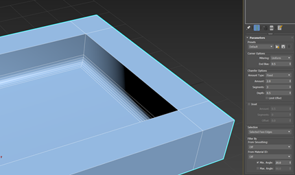
- Zoom into a corner to better see the results. As you can see, the four edges have been chamfered, with even, connected corners. The output is the result of the Uniform option, which is the default Mitering setting on the Corner Options rollout.
- Under Chamfer Options, set Amount to 2.0 to enlarge the chamfer.
- Under Corner Options, set Mitering to Quad.
This creates new quadrilateral polygons around each chamfered edge.The number of polygons is twice the current Segments value, an option which can be increased to get smoother chamfers.
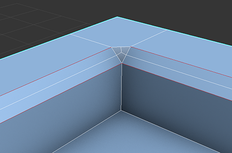
- Under Corner Options, set Mitering to Tri, which replicates the legacy Standard option of previous versions.

Note that the polygons at the corners are now triangles. Triangular polygons can lead to unpredictable results when modeling, so it's better to work with quads whenever possible.
- Set Mitering back to Uniform, and the drag the Depth spinner slowly upward to 1.0 while keeping an eye on the chamfered corner.
Notice that the higher the setting, the more the chamfered area bulges outward, until it's a sharp corner at 1.0. If you want a more rounded chamfer, use a Depth value of between 0.0 and 1.0.
- Set Depth to
0.5 and increase Segments to
3.
This produces a nicely rounded chamfer, with a smooth transition between the adjacent surfaces.
- To compare this result with the legacy chamfer method, set Mitering back to Tri for a moment.
As you can see, the chamfered area is flat again, and there is no deformation because neither the Depth setting nor the Tension setting are available with Tri mitering.
- Set Mitering to Patch and then Radial to see the effects of these corner options. When using a lot of segments, these options can produce higher-resolution results.
- Set Mitering back to Uniform before continuing to Part 3.
Now that you've created the object to chamfer, you'll explore some of the Chamfer modifier options.
Part 3: Change Selection Options
- On Corner Options rollout, enable Uniform mitering again, and then examine the Selection drop-down list.
Currently Selection is set to From Stack, which means that the chamfer is applied to whatever selection exists at the active sub-object level of the object to which the modifier is applied. But what happens if no sub-object level is active?
- To see this, in the modifier stack, click the Editable Poly item.
The stack display updates to show that the Edge level is active.
- Make sure the Show End Result toggle below the stack is on (
 ) and click either the Edge or the Editable Poly item in the stack display.
This sets the object to Object level, with the result that the chamfering is applied to every edge. This is standard behavior.
Although Edge is no longer the active sub-object level on the stack, the edge selection still exists and is available to Chamfer.
- On the modifier stack, click the Chamfer entry, then set Selection to Selected Edges.
The chamfering is once again limited to the edge selection.
The face selection made earlier is also available to Chamfer.
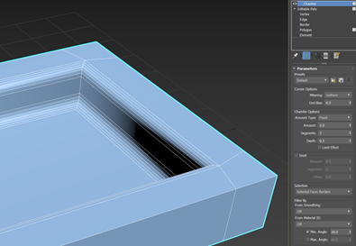
- Set Selection to Selected Face Edges.
This applies the chamfering to all edges of the polygon selection on the stack, including the "inside" edges between adjacent selected polygons. This produces chamfering of the inner vertical edges.
If you prefer to chamfer only the inner horizontal edges, you can use a different option.
- Select Editable Poly again and click on the Polygon button.
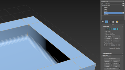
- Turn off Show End Result () to better see your selection. Then select one of the inside walls of the box and hold Shift and click the face next to it. This will select the entire loop of faces.
- Go back to the Chamfer modifier and set Selection to Selected Faces Border.
A border comprises only edges on the perimeter of each contiguous polygon selection. So with the Selected Faces Border option, interior edges such as the vertical corners are not chamfered.
Part 4: Use Crease Weights to Drive Chamfering
- From the Chamfer Options group, set the Min Amount to 0 and the Max Amount to 1.
- In the stack, select Editable Poly and under Selection click Faces.
- Select the four top faces of the box.
- Hold Shift and under Selection click Edges to select the border edges of all the selected faces.
- From the Edge Properties group in the Edit Edges rollout, set the Crease Weight to 0.1.
- Repeat steps 4 and 5 to select the border edges underneath the box, and then repeat step 6 to set the Crease Weight to 1.
- Exit Edge mode and in the stack, click on Chamfer.
- From the Chamfer Options group, adjust the Min Amount and Max Amount to see the effect on the chamfering by the newly applied crease weights.
- To learn more about Chamfer, experiment with the remaining settings. These are all explained in the Chamfer Modifier Reference topic.