ObjectDisplay > Diagnostic Shading
Opens the diagnostic shading control window, which allows you to shade the model using various modes.
Diagnostic Shade
The icons under Shading shade your geometry so you can view and evaluate your surfaces. The various shading modes provide different diagnostic information about surfaces.
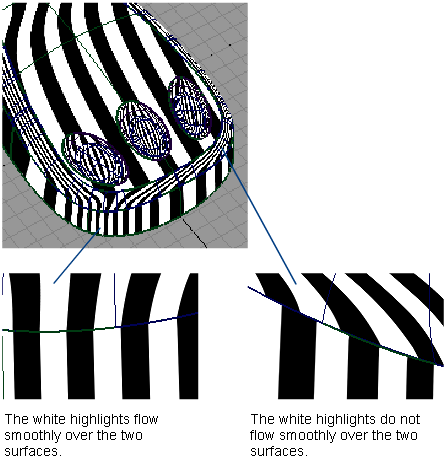
Some tools in diagnostic shading, such as Horizontal/Vertical, simulate light reflecting against the surface of your model. Reflecting light on a surface is a good way to check for any bumps, dents, or other irregularities. Reflections also point out any surfaces that do not meet smoothly.
Curvature Evaluation tools color-code the curvature of your surfaces. Color-coding the curvature is useful when, for example, your model will eventually be made in a material that only bends a certain amount before breaking.
Surface Evaluation contains a draft angle map. This diagnostic tool is useful for products produced through injection molding. If the sides of a mold are too steep, an object cannot part with its mold. Draft Angle evaluation shows which parts of an object are in-draft and which are out-of-draft.
In addition, Surface Evaluation includes a way to map mesh deviations. If you have scanned an object, and are trying to match the scan data with your model, mesh deviation lets you know where the two surfaces are not the same.
You can continue to adjust CVs while diagnostic shading is on.
![]()
Click the white arrowhead in the lower left corner to show or hide options after selecting a shading mode.
Tolerance
Controls how accurately surfaces are tessellated when Tessellator is Fast. The slider range is 0.0001 to 1.0. The default value is 0.1.
The picture shows a surface with the tolerance slider set to 1. The portions where the shading does not entirely meet the wireframe show the triangulation has been quick but not perfectly accurate. This effect is called “nickeling”. If the slider is set to 0.01, the surfaces of the model become completely shaded because the triangulation is more accurate, however, the process takes longer. Choosing a tolerance value means balancing time versus appearance.
The same tolerance value is found in the option window of WindowDisplay > Hardware Shade  .
.
Tessellator
Fast – Tessellates more quickly and less accurately.
Accurate – Tessellates more accurately and more slowly.
When set to Accurate, a check box is added for Limit Edge Length. If this box is checked, a slider is added for Max. Edge Length. Max. Edge Length is the maximum length (in current units) of a triangle created by tessellation.
The same option is used in the option window of WindowDisplay > Hardware Shade .
Layer
Choose a shader from this menu (Isophotes, Curvature, or Horiz/Vert) to layer on top of an already applied diagnostic shader. The default is None.
The parameters of the layered shader appear below the parameters of the original shader in the control window.
New objects
Automatically shades new geometry created by tool operations with the currently assigned diagnostic shader. New objects is on by default.