Use this procedure to add one or more new beams with property settings that you specify. You can add a beam anywhere in the drawing area by specifying a start point and an endpoint, or you can position and size a beam in relation to an existing object. You can also create multiple beams, either one at a time (connected endpoint to start point) or arrayed within boundaries defined by other beams or by column grids, slabs, roof slabs, or walls. The style specified in the tool provides the beam shape, which is extruded along the paths you define in the drawing area.
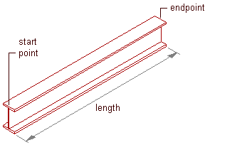
Creating a beam
Optionally, offset the beam from its start point or endpoint.
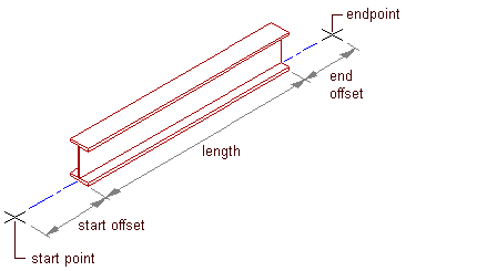
Offsetting a beam
- Open the tool palette that contains the structural beam tool you want to use, and select the tool.
(You may have to scroll to display the desired tool).
Note: Alternatively, you can click


 .
. - On the Properties palette, under General, click Style, and select a structural beam style.
- Specify a value for Bound spaces:
If you want to… Then… allow the beam to be used as a bounding object for associative spaces select Yes. prevent the beam from being used as a bounding object for associative spaces select No. use the bounding setting from the beam style select By Style. - Specify a value for Trim automatically:
If you want… Then… the geometry of the beam to be automatically trimmed to any other structural members, other architectural objects, or linework to which it is logically connected select Yes. prevent the geometry of the beam from being trimmed automatically select No. use the trim setting from the beam style select By Style. Note: This setting affects only the structural member being added. Adding a new structural member will not change the geometry of an existing structural member, regardless of the setting for Trim automatically. - Specify a value for On object:
If you want… Then… layout structural members on a column grid, slab, wall, or polyline select Yes. layout structural members independent from a column grid, slab, wall, or polyline select No. Note: On object is an Add Only property. You may not specify a value for On object when editing a structural member. - Expand Dimensions.
- Specify offsets:
If you want to… Then… offset the beam on its extruded axis at the start point of the beam enter a value for Start offset. A positive value shortens the beam on its axis, while a negative value lengthens the beam on its axis. offset the beam on its extruded axis at the endpoint of the beam enter a value for End offset. A positive value lengthens the beam on its axis, while a negative value shortens the beam on its axis. - Enter a value for Roll.
This value specifies the orientation of the beam relative to its extruded axis in terms of degrees of roll. A positive value rolls the beam counterclockwise when viewed from its end to its start.
- Specify the beam justification, which positions the beam shape in relation to its extruded axis when you draw the beam:
If you want to… Then… position the axis of the beam along the centroid of the beam shape select Baseline for Justify. Note: This applies to members created with styles from the Structural Member Catalog only.position the axis of the beam along one of 9 positions on the beam shape select one of the 9 positions for Justify. Note: These positions are defined at a roll of zero, viewing the beam from the end to the start.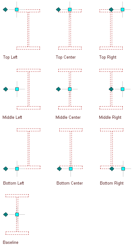
Justification options for a beam
- Select a Layout type to specify how a beam is positioned in relation to a highlighted edge of a column grid, slab, roof slab, or wall:
If you want to position the beam… Then… along the highlighted edge of the object select Edge for Layout type. within the boundaries of the object (from one edge to an opposite edge or edges) select Fill for Layout type. - If Layout type is Fill, and you want to array multiple beams between 2 existing beams or within a column grid, slab, roof slab, or wall, expand Layout and select Yes for Array.
- Specify the layout method for the array:
If you want to array beams… Then… so that they create a specific number of equal-sized bays select Space evenly for Layout method, and enter a value for Number of bays. at a specific distance from each other select Repeat for Layout method, and enter a value for Bay size. Tip: After specifying the desired settings, you can move or hide the Properties palette to expose more of the drawing area. - If you want to offset the new beams from the elevation of the current level, double-click the Elevation value on the application status bar at the bottom of the workspace, enter an elevation value (or specify a point on an existing object in the drawing area), click OK, and then click the Z-snap button to the right of the Elevation value.
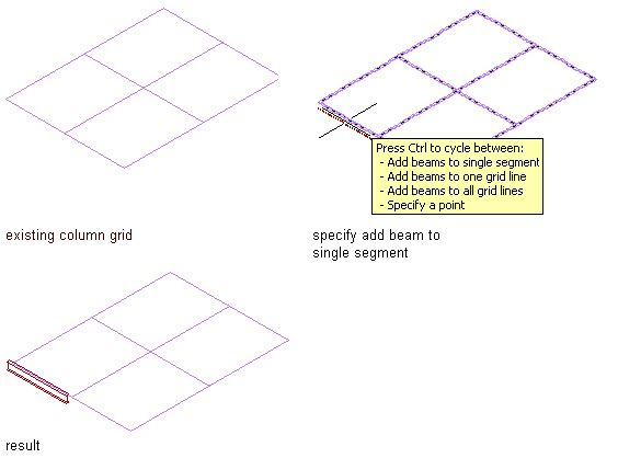
Adding a beam to a single segment
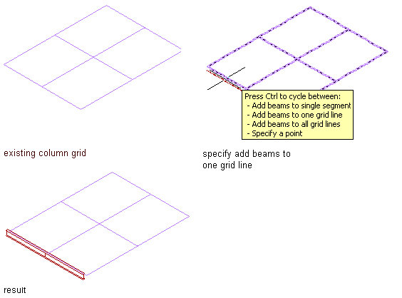
Adding beams to one grid line
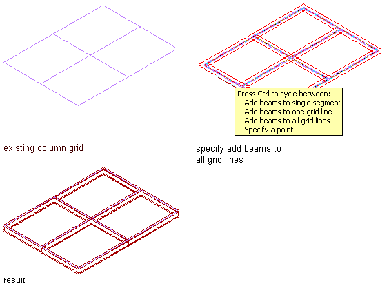
Adding beams to all grid lines
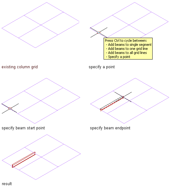
Adding a beam to a specified point
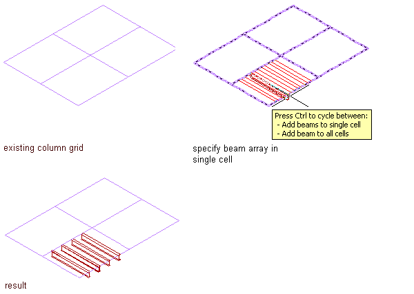
Adding a beam array to a single cell
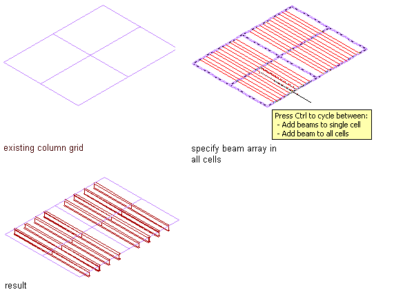
Adding a beam array to all cells
- Position the new beams in the drawing area:
If you want to… Then… create a single beam independent of other objects specify a start point and an endpoint for the beam, and then press Enter. create multiple beams independent of other objects but connected to each other using the endpoint of one beam as the start point of the next beam specify a start point and an endpoint, and then specify additional endpoints as required. Press Enter to end the command. create a beam that is connected to an existing structural member specify a start point and an endpoint, one of which must be on the axis or the endpoint of the existing member. Press Enterto end the command. add a beam along one or more edges of a slab, roof slab, or wall (assuming Layout type is Edge) move the cursor over an edge of the object until a preview of the beam is displayed, and then click to add a beam along that edge, or press Ctrl and click to add beams along all edges of the object. Press Enter to end the command. add a beam along one or more segments of a column grid (assuming Layout type is Edge) move the cursor over a segment of the grid until a preview of the beam is displayed, and then click to add a beam along that segment; or press Ctrl and click to add beams along all segments in that grid line; or press Ctrl twice and click to add beams along all segments in the grid. Press Enter to end the command. add a beam that spans a slab, roof slab, wall, or column grid cell from edge to edge at an angle of 90 degrees (assuming Layout type is Fill) move the cursor over the object edge or column grid segment until a preview of the beam is displayed in the desired position perpendicular to the edge/segment, and then click. Press Enter to end the command. add a beam that spans a slab, roof slab, wall, or column grid cell from edge to edge at an angle other than 90 degrees (assuming Layout type is Fill) move the cursor over the object edge or column grid segment until a preview of the beam is displayed, enter a value for the desired angle, press Enter, and then click. Press Enter to end the command. array beams between 2 structural members (assuming Array is Yes) move the cursor over one of the structural members until its baseline is displayed, click that member, specify a point on the second member, and press Enter. New beams are arrayed according to the Layout Method selected on the Properties palette and at an angle determined by the point you specify on the second member. Press Enter to end the command. array beams perpendicularly within a slab, roof slab, wall, or one or more cells of a column grid (assuming Array is Yes) move the cursor over an edge until a preview of the array is displayed, and click. New beams are arrayed perpendicular to the selected edge according to the Layout Method selected on the Properties palette. If you want to add the array to all cells of a column grid, press Ctrl before clicking. Press Enter to end the command. array beams at an angle other than 90 degrees within a slab, roof slab, wall, or one or more cells of a column grid (assuming Array is Yes) move the cursor over an edge until a preview of the array is displayed, enter a value for the desired angle, press Enter, and then click. New beams are arrayed at the specified angle according to the Layout Method selected on the Properties palette. If you want to add the array to all cells of a column grid, press Ctrl before clicking. Press Enter to end the command.