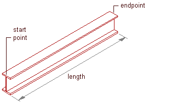
Use this procedure to add one or more new beams that have the property settings specified in the structural beam tool that you select. You can add a beam anywhere in the drawing area by specifying a start point and an endpoint, or you can position and size a beam in relation to an edge of an existing object. The style specified in the tool provides the beam shape, which is extruded along the path you define in the drawing area.

Creating a beam
- Open the tool palette that contains the structural beam tool you want to use, and select the tool. Tip: You may have to scroll to display the desired tool. After selecting it, you can move or hide the Properties palette to expose more of the drawing area.Note: Alternatively, you can click


 .
. 
- If you want to offset the new beam(s) from the elevation of the current level, double-click the Elevation value on the application status bar at the bottom of the workspace, enter an elevation value (or specify a point on an existing object in the drawing area), click OK, and then click the Z-snap button to the right of the Elevation Value.
- Position the new beam(s) in the drawing area:
If you want to… Then… create a single beam independent of other objects specify a start point and an endpoint for the beam, and then press Enter. create multiple beams independent of other objects but connected to each other using the endpoint of one beam as the start point of the next beam specify a start point and an endpoint, and then specify additional endpoints as required. Press Enter to end the command. create a beam that is connected to an existing structural member specify a start point and an endpoint, one of which must be on the axis or the endpoint of the existing member. Press Enter to end the command. add beams along one or more edges of a slab, roof slab, or wall move the cursor over an edge of the object to display a preview of the beam, and then click to add a beam along that edge, or press Ctrl and click to add beams along all edges of the object. Press Enterto end the command. add beams along one or more segments of a column grid move the cursor over a segment of the grid to display a preview of the beam, and then click to add a beam along that segment; or press Ctrl and click to add beams along all segments in that grid line; or press Ctrl twice and click to add beams along all segments in the grid. Press Enter to end the command. Note: If you want to add a beam that spans an object from edge to edge rather than lying along one of its edges, you can change the Layout type setting from Edge to Fill on the Properties palette.