Use Circuit Builder to insert and annotate a circuit based on an existing circuit.
When a new circuit is inserted, you can reference an existing circuit picked from a list of circuits pulled from the active project. The components, values, descriptions, and tag assignments from the selected circuit, become defaults for the new circuit. Tags are recalculated if the option “Retag new components” is selected.
In this exercise, you insert a 3-phase motor control circuit referencing the one-line motor control circuit inserted earlier.
- Start a new blank drawing and save it as Three-Line.dwg.
- In Project Manager, right-click on the project name and select Add Active Drawing.
- Click Yes to apply the project default values to the drawing settings.
-
Click
 . Find
- Insert a 3-phase ladder.
-
Click
. Find
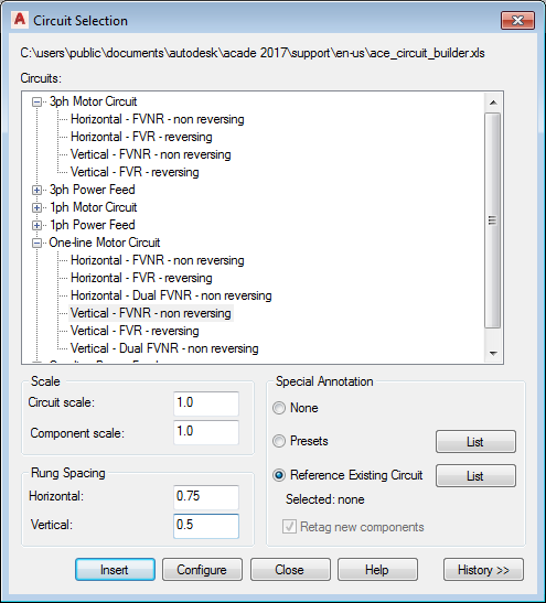
- The Circuit Selection dialog box displays.
- Select 3ph Motor Circuit: Horizontal - FVNR - non reversing.
- Select Reference Existing Circuit.
- Select the List button.
The Existing Circuits dialog box displays.
- Select the one-line motor control circuit inserted on One-Line.dwg, MOT1.
- Click OK.
- Turn off the Retag new components check box.
This directs Circuit Builder to use the tags from the one-line circuit for the components with matching marker block code values.
- Select Configure.
- Select an insertion point on the bus for the new circuit.
- Verify that the same circuit elements as the referenced one-line motor circuit are selected. The default options are based on the referenced circuit.
Circuit Elements
Select
Motor symbol
Motor: 3ph motor
Ground/PE wire connection: No
Disconnecting means
Main Disconnect: Disconnect switch and Fuses
Include N.O. Auxiliary contact: No
Control transformer and circuit - non-reversing
Include control circuit: None
Power Factor correction
Include power factor correction capacitor: None
Overloads
Overload elements: None
Include N.O. auxiliary contact: No
Motor terminal connections
Motor connection terminals: None
Cable marker
Cable: Yes
Safety disconnect at the load
Safety disconnect: None
Include N.O. auxiliary contact: No
-
 Click to insert all circuit elements.
- Click Done.
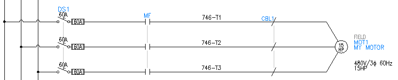
The circuit is inserted and the component values from the one-line circuit are applied. The motor symbol receives the same catalog value and horsepower rating. The main disconnect switch receives the same rating values for the switch and the fuses. The motor symbol receives the values modified on the one-line circuit after it was inserted.