Use Circuit Builder to configure and insert a dual power feed circuit.
A dual circuit has two distinct circuits running off the same bus-tap. Each circuit can be independently configured.
-
Click
 . Find
- The Circuit Selection dialog box displays.
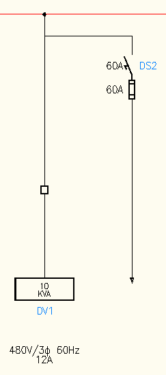
- Select One-line Power Feed: Vertical - Dual feed.
- Click Configure.
- Specify an insertion point on the one-line bus.
The Circuit Configuration dialog box displays. Notice that some circuit elements have a “(2)” prefix. These elements make up the second circuit in the dual circuit.
- In the Circuit Elements section, select Load Setup.
-
 In the Setup & Annotations: Load Setup section, select the Browse button.
The Select Load dialog box displays.
- Select Type: Transformer, Voltage (V): 480, and Phase: 3.
- Select an entry from the grid and click OK.
- Continue selecting Circuit Elements for the first circuit:
Load: Generic box
Disconnecting means: None
Terminal strip or connector: Square
Cable marker: None
- In the Circuit Elements section, select (2) Load Setup.
-
In the Setup & Annotations: Load Setup section, select the Browse button.
The Select Load dialog box displays.
- Select Type: Transformer, Voltage (V): 480, and Phase: 3.
- Select an entry from the grid and click OK.
- Continue selecting Circuit Elements for the second circuit:
(2) Load: Source arrow
(2) Disconnecting means: Disconnect switch and fuses
(2) Terminal strip or connector: None
(2) Cable marker: None
-
 Click to insert all circuit elements.
- Click Done.
- Save the drawing.