Setting up layers
- In a blank AutoCAD Electrical toolset drawing,
Click


 . Find
- On the Alert dialog box, click OK to add the WD_M block.
- In the Drawing Properties dialog box, click the Style tab.
You can select the default Fan-In/Out marker style here along with defining the layers for the wires. Notice that the default layer name for fan in/out single line layers is "_MULTI_WIRE."
- In the Drawing Properties dialog box, click OK.
- Click the AutoCAD Layer Properties Manager tool.
- In the Layer Properties Manager dialog box, change the color of "_MULTI_WIRE" to red and the color of "WIRES" to blue for this example. The color difference illustrates how the feature works.
- In the Layer Properties Manager dialog box, click OK.
Inserting components
-
Click


 . Find
- In the Insert Component: JIC Schematic Symbols dialog box, select Push Buttons.
- In the JIC: Push Buttons dialog box, select Push Button N.O.
- Press F9 to turn on SNAP.
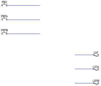
- Insert the push button anywhere on the left-hand side of the drawing.
- In the Insert/Edit Component dialog box, click OK-Repeat to insert two more push buttons directly below the first one.
- In the Insert/Edit Component dialog box, click OK after the last push button is inserted on the drawing.
- Repeat to insert three Limit Switches N.O. Insert the limit switches anywhere on the right-hand side of the drawing (slightly below the push buttons you inserted).

Adding wires
-
Click


 . Find
- Add a wire to the top push button. Drag the wire to the right.
- Repeat for the other two push buttons.
- Add a wire to each of the limit switches. Drag the wires to the left.
- Press F9 to turn off SNAP.
- Select all of the wires and verify that they were created on the WIRES layer.

Adding source and destination markers
-
Click


 . Find
- In the Fan In/Out Source dialog box, select Solid as the Source marker style.
- Click the left button to set the wire connection orientation.

- Select in the middle of the wire that is connected to the top push button.
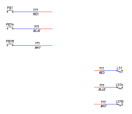
- In the Signal - Source Code dialog box, enter "cbla" as the code and "RED" as the description.
If you enter the color of the wire in the Description field, AutoCAD Electrical toolset reports use this information in the Wire Color field.
- Click OK.
- In the Source/Destination Signal markers (for Fan In/Out) dialog box, click Yes to insert the matching destination marker now. Note:
Because the destination wires are nearby, it is easier to insert them right away. If the wires were on another drawing you could wait until later to add the destination markers.
- In the Fan-In/Fan-Out Signal Destination dialog box, select Solid as the destination marker style.
- Click the right button to set the wire connection orientation.

- Select in the middle of the wire connected to the top limit switch.
Notice that the wires for both change from blue to red, and the description RED appears on both.
AutoCAD Electrical toolset breaks the wire and changes the appropriate wire piece to the defined layer. When inserting a source marker the wire coming out of the marker changes; when inserting a destination marker, the wire going into the marker changes.

You are prompted to define the next source.
- Repeat for the middle and bottom wires for each group.
For the middle wire: In the Signal - Source Code dialog box, click Use to enter "CBLA-01" as the code and enter "BLUE" as the description.
For the bottom wire: In the Signal - Source Code dialog box, click Use to enter "CBLA-02" as the code and enter "WHT" as the description.
Notice that the wires change from blue to red, and the descriptions BLUE and WHT display on both sets of wires.
- Press Esc to exit the command.
- Select all of the wires and verify that they are on the _MULTI_WIRE layer.

Creating connecting wires
- At the command line, type L and press Enter.
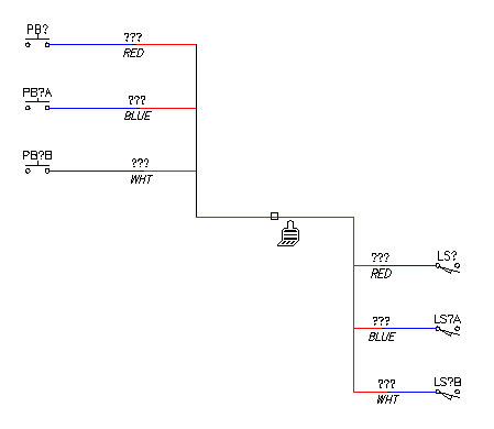
- Click the end of the uppermost wire and drag down across each of the wires connected to the push buttons. Continue dragging past the push buttons and click.
- Drag your cursor to the right to create a horizontal line, and click.
- Drag down across the ends of the wires connected to the limit switches, ending on the bottom wire and click. Press Enter to create the lines.

- Type MA at the command prompt to run the AutoCAD MATCHPROP command.
- Click the wire connected to the top limit switch.
- Click each of the lines you just created. The lines change from black to red since they are taking on the properties of the wire you selected.

- Press Enter to exit the command.
Adding cable markers
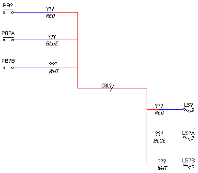
At this point, you have established the link between the push buttons and the limit switches. You can now include a cable marker identifier that is associated with these wire connections in various wire and cable reports.
-
Click


 . Find
- Select to insert a cable marker.
- Insert the cable marker on the horizontal line.
- In the Insert/Edit Cable Marker (Parent wire) dialog box, click Catalog Data Lookup.
- In the Catalog Browser dialog box, search for and select a 3 conductor cable and click OK.
- In the Insert/Edit Cable Marker (Parent wire) dialog box, delete the wire color/id value (BLK), and click OK.
- In the Insert Some Child Components dialog box, click Close.
