Use the Project Manager to manage your P&ID drawings.
From here, you can create a drawing and modify any drawing properties.
Create a new drawing
- Click
 . Find
- In the Project Manager, click the New Drawing tool.

- In the Create New Drawing dialog box, specify:
Name: AEGS13
Template: Mouse over the edit box to verify ACAD_Electrical.dwt is specified
If ACAD_Electrical.dwt is not specified, click Browse. Select it from the list of available templates.
Description 1: P&ID Example
Click OK.
Note: If you want to set the component, wire number, cross-reference, style, and drawing format settings, click OK-Properties to proceed to Drawing Properties dialog box. - Enter DSETTINGS at the command prompt.
- In the Drafting Settings dialog box Snap and Grid tab, turn on Snap and Grid and set the size of both to 0.125.
- Click OK.
- Click
. Find
- In the Drawing Properties dialog box Drawing Format tab, Scale section, make sure that the feature scale multiplier is set to 1.0 inch.
- Click OK.
Note: For metric unit, the following settings are recommended so that the wire connection points are placed on the grids for easier drafting. Grid and Snap Size = 2.5 mm; Feature scale multiplier =20 (scale factor = 20).
Set up wire layers
- Click
. Find
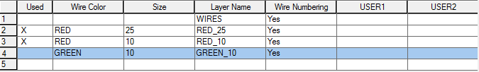
- In the Create/Edit Wire Type dialog box, click in the Wire Type #2 row and specify:
Wire Color: RED
Size: 25
The Layer Name is automatically created. The name RED_25 is assigned to the wire layer you are creating.
- Click Color.
- In the Select Color dialog box, select red and click OK.
- Click Linetype.
- In the Select Linetype dialog box, select Continuous and click OK.
- Click Lineweight.
- In the Select Lineweight dialog box, select 0.30 and click OK.
For this example, create three more wire types using the Create/Edit Wire Type dialog box.
- In the Create/Edit Wire Type dialog box, specify:
Wire Type #3
Wire Color: RED
Size: 10
Color: Red
Linetype: Hidden2
Lineweight: default
Wire Type #4
Wire Color: GREEN
Size: 10
Color: Green
 Note: For pipe runs in P&ID drawings, include the different linetypes from the acade.lin file. You can set up the wire types for pipes at the beginning of the drawing or before creating the pipes.
 - To set the Linetype for the GREEN_10 wire layer, click Linetype.
- In the Select Linetype dialog box, click Load.
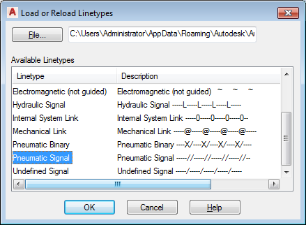
- In the Load or Reload Linetypes dialog box, click File.
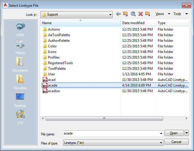
- In the Select Linetype File dialog box, select acade.lin and click Open.
Note: The default location for the acade.lin file is \Users\{username}\AppData\Roaming\Autodesk\AutoCAD Electrical {version}\{release number}\{country code}\Support.
- In the Load or Reload Linetypes dialog box, select Pneumatic Signal and click OK.
- In the Select Linetype dialog box, select Pneumatic Signal and click OK.
- In the Create/Edit Wire Type dialog box, click OK.