Add ladder rungs and draw wires.
You can start or end a wire segment in empty space, from an existing wire segment, or from an existing component. If you start from a component, the wire segment snaps to the wire connection terminal closest to your pick point on that symbol. If the wire segment ends at another wire segment, a DOT (block name wddot.dwg) is applied if appropriate. If it ends at another component, the segment connects to the wire connection terminal closest to your pick point on that symbol.
Insert wiring
- If AEGS is not the active project, in the Project Manager, right-click AEGS and select Activate.
- In the Project Manager, double-click AEGS to expand the drawing list.
- In the Project Manager, Project Drawing List, double-click AEGS04.dwg.
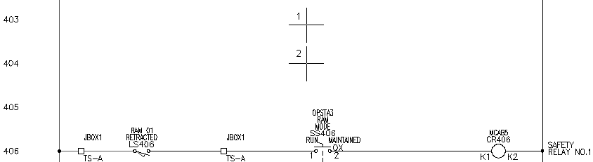
- Zoom in on the upper left corner of the drawing. Make sure the hot and neutral vertical wires are displayed.
- Click
 . Find
- Respond to the prompts as follows:
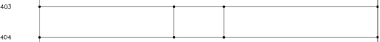
Add rung passing through this location or [wiretype (T)]:
Select a location between the two vertical bus wires beside line reference 403 (1)
Add rung passing through this location or [wiretype (T)]:
Select a location between the two vertical bus wires beside line reference 404, underneath the newly created rung (2), pressENTER
Two horizontal wires are created automatically between the vertical bus wires at the closest line reference location.
Create two vertical wires between two horizontal wires
- Click
. Find
- Respond to the prompts as follows:
Specify wire start or [wireType/X=show connections]:
Select the top wire at line reference 403(1)
Specify wire end or [V=start Vertical/H=start Horizontal/Continue]: Select the lower wire at line reference 404 (2)
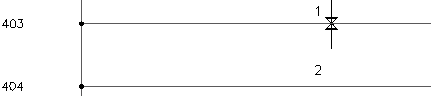
The color of temporary graphics changes for a new wire when AutoCAD Electrical toolset can connect the wire to an existing wire.
Each component wire connection point displays as a green x at the wire connection when you enter X + ENTER during wire insertion. If you pan or zoom, repeat the command to view the wire connection points.
- Insert another wire to the right of the new wire.
- Press
ENTER to exit the command.
The inserted wires resemble the following image.