Insert wire connection attributes and related pin attributes.
If an X?TERMxx of the component (for example, "X2TERM01") wire connection-point attribute lies within the small trap distance of the end of a wire, then AutoCAD Electrical toolset interprets the component connected to the wire. The only time the trap distance changes is when you change the Feature Scale Multiplier in the Drawing (or Project) Properties  Drawing Format dialog box.
A wire connection attribute can have a related terminal text attribute, TERMxx, and terminal description attribute, TERMDESCxx. The "xx" is a two-digit number (starting at 01) that is used to match up with the corresponding X?TERMxx wire connection attribute.
Insert connection points
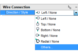
- In the Symbol Builder Attribute Editor, expand the Wire Connection section.
- In the Direction / Style list, select Others.
- On the Insert Wire Connection dialog box select Terminal Style: Screw.
This terminal style inserts both the graphic to represent the screw and the wire connection points.
- Check Use this configuration as default. It directs Symbol Builder to use the current Terminal Style and Scale as the default in the Symbol Builder Attribute Editor.
- Select Connection direction: Left & Top.
It determines the direction the wire attaches to the component.
- Enter “L” as the value for TERM01 in Pin Information.
- Select X2TERMDESC01 in Pin Information and click Delete.
- Click Insert.
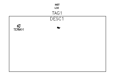
- Select the Insert Wire Connection tool and insert the terminal in the upper left-hand corner as shown.
Note: Always use AutoCAD Snap to insert the wire connection point.
- Back on the Symbol Builder Attribute Editor, expand the Wire Connection Direction / Style list and select Right & Top / Screw.
- Select the Insert Wire Connection tool and insert the terminal in the upper right-hand corner.

You can continue to insert wire connections until you press ENTER by entering the characters indicated in the command line prompt followed by a space. You can also select from the Direction / Style list.
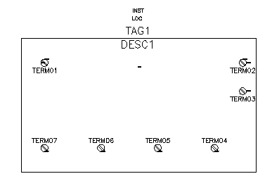
- Insert the rest of the terminals as follows:
TERM03: Right
Insertion Point: below TERM02
TERM04: Bottom
Insertion Point: in the lower right-hand corner
TERM05: Bottom
Insertion Point: to the left of TERM04
TERM06: Bottom
Insertion Point: to the left of TERM05
TERM07: Bottom
Insertion Point: to the left of TERM06
- Press Enter if necessary to return to the command prompt.
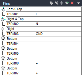
- On the Symbol Builder Attribute Editor, expand the Pins section. Enter the Pin values as follows:
TERM02 : N
TERM03 : GND
TERM04 : -
TERM05 : -
TERM06 : +
TERM07 : +
Your drawing looks like the following image: