Dynamically build connectors by defining the connector parameters such as the number of pins, pin spacing, and pin values.
The Insert Connector tool generates a connector symbol from user-defined parameters. The symbol is created on the fly and inserted as a block insert into your active drawing file. Since they are created on an as needed basis, it eliminates the need for you to create and maintain a library of connector symbols.
Change drawing properties
- If AEGS is not the active project, in the Project Manager, right-click AEGS and select Activate.
- In the Project Manager, double-click AEGS to expand the drawing list.
- Open AEGS10.dwg.
- Click
 . Find
- On the Drawing Properties Components dialog box, select Sequential.
- On the Drawing Properties Wire Numbers dialog box, New Wire Number Placement section, select In-Line.
- Click OK.
Add connectors to the drawing
- Click
. Find
- On the Insert Connector dialog box, specify:
Pin Spacing: 1.0
Pin Count: 15
Fixed Spacing
Pin List: 1
Insert All
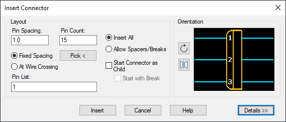
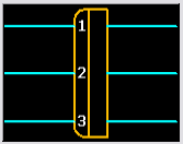
- Click the Flip button to flip the connector about its long axis.

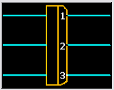
The preview looks like the following image.
- Click Insert.
A preview outline of the connector displays for placement on the drawing. It shows rounded corners for the plug side of the connector. An “x” indicates the insertion point of the connector. An arrow indicates the plug side wire connection direction for plug/receptacle or plug-only connector inserts or shows the wire connection direction for a receptacle-only connector insert.
Note: Before committing the connector outline to the drawing, press TAB to flip the connector through four different orientations. Or, press the V key to switch between vertical and horizontal orientations. - Respond to the prompts as follows:
Specify insertion point or [Z=zoom, P=pan, X=wire crossing, V=horizontal/vertical, TAB=flip]:
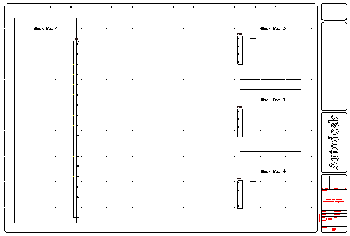
Select to place the connector in the middle of the right-hand border of Black Box 1
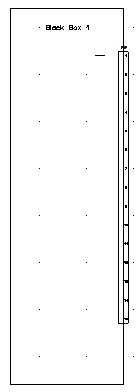
The connector was automatically assigned a component tag of PJ1.
- Click
. Find
- On the Insert Connector dialog box, specify:
Pin Spacing: 0.75
Pin Count: 4
Fixed Spacing
Pin List: A
Insert All
- Click the Flip button to flip the connector.
The preview looks like the following image.
- Click Insert.
- Respond to the prompts as follows:
Specify insertion point or [Z=zoom, P=pan, X=wire crossing, V=horizontal/vertical, TAB=flip]:
Select to place the connector in the middle of the left-hand border of Black Box 2
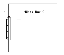
The connector was automatically assigned a component tag of PJ2.
- Repeat steps 6 - 10 to place connectors on Black Box 3 and Black Box 4.
The connectors are assigned tags PJ3 and PJ4 respectively.