Use the Insert Wire and Multiple Bus tools to add wires between connectors.
Black Box 1 is associated to a larger component such as a power box. Black Box 2 - Black Box 4 are smaller components that are part of the power box. The components must be wired together. The easiest way to do it is to use the Insert Wire and Multiple Wire Bus tools.
Wire the connectors together
- Click
 . Find
- Respond to the prompts as follows:
Specify wire start or [wireType/X=show connections]:
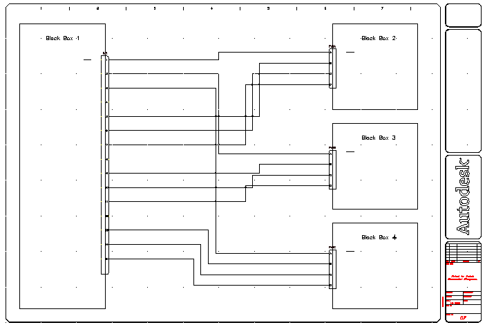
Click PJ1 at pin 1 on Black Box 1
Specify wire end or [Continue]: Click PJ2 at pin A on Black Box 2
- Repeat to connect PJ1 (Pin 2) to PJ3 (Pin A) and PJ1 (Pin 3) to PJ4 (Pin A). Right-click to exit the command.
Notice that the Insert Wire tool drew the wire between the connectors while avoiding any existing geometry on the screen.
- Click
. Find
- On the Multiple Wire Bus dialog box, specify:
Horizontal Spacing: 0.75
Vertical Spacing: 0.50
Starting at: Component (Multiple Wires)
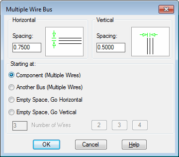
- Click OK.
- Respond to the prompts as follows:
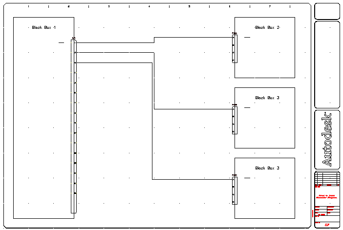
Window select starting wire connection points
Select pins 5-7 on Black Box 1 (1) and right-click
to (T= wiretype):
Drag the wires to the right past the three wires you inserted,
to Point (Continue/Flip):
Drag up the wires towards PJ2 on Black Box 2, enter C and press ENTER (to continue and lock the drag)
to (Continue/Flip):
Drag the wires to the right and connect to pins B-D on PJ2 (2)
- Click
. Find
- On the Multiple Wire Bus dialog box, click OK to use the previous settings.
- Respond to the prompts as follows:
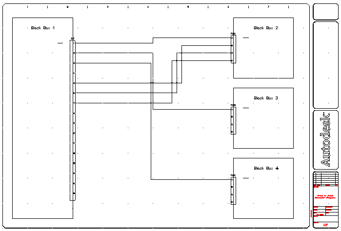
Window select starting wire connection points:
Select pins 9-11 on Black Box 1 and right-click
to (T= wiretype):
Drag the wires to the right,
to Point (Continue/Flip):
Drag up the wires towards PJ3 on Black Box 3, enterC, and press ENTER(to continue and lock the drag)
to (Continue/Flip):
Drag the wires to the right and connect to pins B-D on PJ3
- Click
. Find
- On the Multiple Wire Bus dialog box, click OK to use the previous settings.
- Respond to the prompts as follows:
Window select starting wire connection points:
Select pins 13-15 on Black Box 1 and pressENTER
to (T= wiretype):
Drag the wires to the right,
to Point (Continue/Flip):
Drag the wires down towards PJ4 on Black Box 4, pressC,and pressENTER(to continue and lock the drag)
to (Continue/Flip):
Drag the wires to the right and connect to pins B-D on PJ4