Insert a source arrow on a wire that breaks and continues in a new location.
AutoCAD Electrical toolset uses a named source/destination concept. You identify a wire network to be the source, insert a source arrow on that network, and assign a source code name to it. On the wire network that is to be a continuation of the same wire number (whether on the same drawing or a different drawing in the project), insert a destination arrow. Give it the same code name that you gave to its source. It matches source code names with destination names and copies source wire numbers over to the destination wire networks.
Attach a source signal arrow
- Open AEGS03.dwg.
- Click
 . Find
- Respond to the prompts as follows:
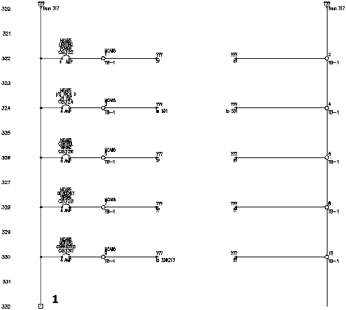
Select wire end for Source:
Select the end of the hot wire on the schematic on the right side of the drawing at line reference 332 (1)
- In the Signal - Source Code dialog box, specify:
Code: 24 VDC
Signal Arrow Style: 1
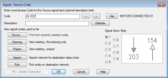
AutoCAD Electrical toolset allows one description line on a source arrow. This description can then be carried over to the associated destination arrow. You can define some default description lines to make them easier to enter without typing them in each time. AutoCAD Electrical toolset looks for a file called WDSRCDST.WDD. This file is a simple text file with each line being read as a separate description. If this file exists, the Defaults button is available on the Signal - Source Code and Insert Destination Code dialog boxes.
- Click OK.
- In the Source/Destination Signal Arrows dialog box, click No.
Note: Click No to insert the signal arrows on the next drawing. Click OK to insert the signal arrows on the current drawing.
-
To access AEGS04.dwg
Click. Find
Now you are ready to insert a destination signal arrow.