Attach a destination signal to a wire segment of a wire network and relate it to the source signal arrow.
After the source signal arrow is attached to a wire in the drawing, you can attach a destination signal to a wire segment of a wire network. It enables the wire number assigned to another source wire network to carry over to the current network automatically.
Attach a destination signal
- Click
 . Find
- Respond to the prompts as follows:
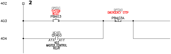
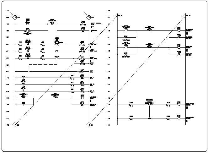
Select wire end for Destination:
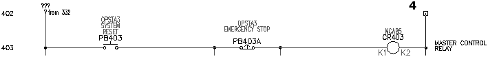
Select the top of the hot wire on the schematic on the left side of the drawing at line reference 402 (2)
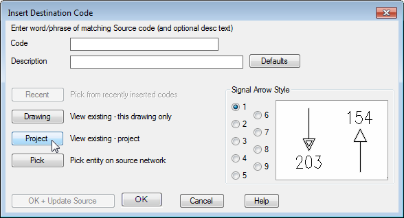
- In the Insert Destination Code dialog box, click Project.
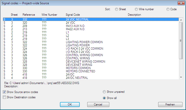
- In the Signal codes -- Project-wide Source dialog box, select the following:
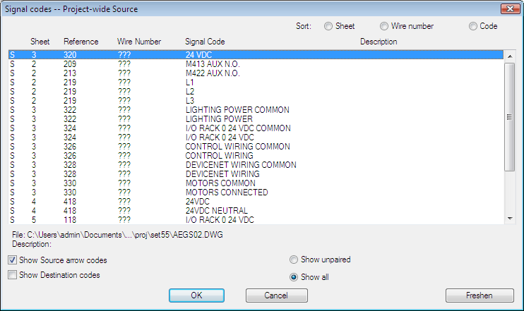
- Click OK.
- In the Insert Destination Code dialog box, verify:
Code: 24 VDC
Signal Arrow Style: 1
Click OK + Update Source.
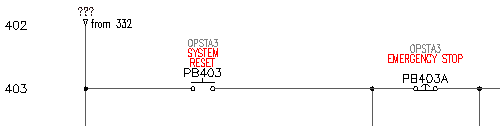
The cross-references for your signal insert into the drawing above the hot wire.
Attach source and destination signals to the neutral wires.
-
To return to AEGS03.dwg
Click. Find
- Click
. Find
- Respond to the prompts as follows:
Select wire end for Source:
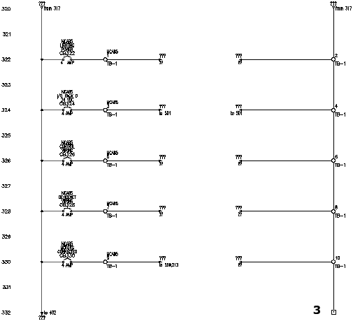
Select the bottom of the neutral wire at line reference 332 (3)
- In the Signal - Source Code dialog box, specify:
Code: 24 VDC NEUTRAL
Click OK.
- In the Source/Destination Signal Arrows dialog box, click No.
Note: Click No to insert the signal arrows on the next drawing. Click OK to insert the signal arrows on the current drawing.
-
To open AEGS04.dwg
Click. Find
- Click
. Find
- Respond to the prompts as follows:
Select wire end for Destination:
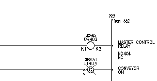
Select the top of the neutral wire at line reference 402 (4)
- In the Insert Destination Code dialog box, click Project.
- In the Signal codes -- Project-wide Source dialog box, select the following:
- Click OK.
- In the Insert Destination Code dialog box, verify:
Code: 24 VDC NEUTRAL
Signal Arrow Style: 1
Click OK + Update Source.
Note: If asked to change the destination wire layer, click Yes.The cross-references for your signal insert into the drawing above the neutral wire.
- Click
 . Find
Temporary graphics illustrate the flow of the signals on your drawings.
 Note: There is no limit to the number of source and destination links you can set up. One source network can jump to multiple destinations on one or many drawings. A wire can carry both a destination signal and a source signal pointing to the next daisy-chained destination.