Insert a parent component, and assign description, location, and catalog values.
AutoCAD Electrical toolset employs a parent/child relationship for schematic components. The parent coil symbol and the child contact symbols represent a relay coil with a certain number of contacts. When the parent coil symbol is inserted, it is assigned a unique component tag. When the child contact symbols are inserted, the child is related to the parent and the parent tag is assigned to the child symbol.
In this exercise, you insert components on the wires previously defined in AEGS04.dwg.
Insert a parent component
- If AEGS is not the active project, in the Project Manager, right-click AEGS and select Activate.
- In the Project Manager, double-click AEGS to expand the drawing list.
- In the Project Manager, Project Drawing List, double-click AEGS04.dwg.
- Zoom in on the upper left corner of the drawing.
- Click
 . Find
- In the Insert Component: JIC Schematic Symbols dialog box, click Relays/ Contacts.

- In the JIC: Relays and Contacts dialog box, click Relay Coil.

- Respond to the prompts as follows:
Specify insertion point:
Position the component on the wire at line reference 403 near the neutral wire and click (1)
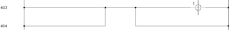
If you select directly on the wire or near to it, the coil symbol breaks the underlying ladder wire and reconnects. If the underlying wire did not break, you did not select close enough to the wire. To try again, click Cancel on the Insert/Edit Component dialog box. Right-click or press ENTER to repeat the command. Turning on Snap helps (0.125 is a good setting to use).
This tool inserts components into alignment with underlying wires, it does not align components side-to-side. If you want to insert components in neat columns, you have three options: use AutoCAD Snap when inserting components; use the Scoot command to move components and connected wires in place; or use the Align Component tool.
- In the Insert/Edit Component dialog box, verify that the Component Tag is set to CR403.
AutoCAD Electrical toolset automatically determines the unique tag name for the new relay based on the line reference location that you inserted the symbol on. “CR” indicates that it is a control relay and “403” indicates that the symbol is on line reference 403. If you inserted this symbol on line reference 404 then the tag name would be “CR404.”
- In the Catalog Data section, click Lookup.
- On the Catalog Browser dialog box, enter AB "TYPE P" 120VAC as the search string.
- Click
 .
.
- Select 700-P200A1.
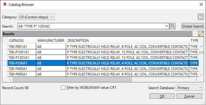
- In the Catalog Browser dialog box, click OK.
The selected manufacturer code and catalog number display in the Insert/Edit Component dialog box. When you click OK on the dialog box, the values transfers to the symbol.
Note: Sample catalog information is provided with AutoCAD Electrical toolset in Access Database format (.mdb). If your company uses its own internal coding system instead of manufacturer catalog numbers, substitute those numbers into the catalog database. - In the Insert/Edit Component dialog box, Description section, specify:
Line 1: MASTER CONTROL
Line 2: RELAY
Up to three lines of description text can be entered as a description for components. If the third description line is unavailable, the symbol does not carry an attribute for a third line of description.
Note: You can specify a description by entering text or by clicking Defaults to select from a list of standard component descriptions. - In the Insert/Edit Component dialog box, Location code section, click Drawing.
AutoCAD Electrical toolset does a quick read of the drawing file and returns a list of all location codes used so far.
- In the All Locations - Drawing dialog box, select MCAB5 and click OK.
Note: You can also include an external “LOC” location list in the project “LOC” list to help with consistency. To use this feature, create a file called default.loc and put it in an AutoCAD Electrical toolset search directory. The format for this text file is each location on its own line in the file with no leading spaces. You can also create a project-specific file by naming it the same as your project but with a .loc extension.
- In the Insert/Edit Component dialog box, the pin values are inserted based on the selected catalog number:
Pins: 1: K1
Pins: 2: K2
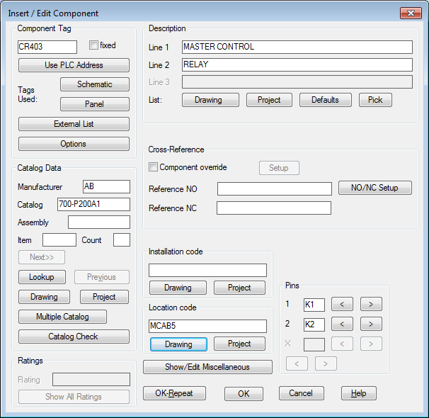
- In the Insert/Edit Component dialog box, click OK.
Any values entered here are saved as attribute values on the symbol itself.