Scoot a component along a wire, and insert child components.
If the component was not inserted in the correct location, you can scoot the component. Use the Scoot tool to select a component or wire number and slide it back and forth along the wire while keeping everything connected. You can select a wire or a whole rung of circuitry and scoot it to a new position. If there are any parent components among the scooted items, you are asked if you want to retag the scooted components.
The Scoot tool works on wire numbers, components, terminals, PLC I/O modules, jogs in dashed link lines, signal arrows, wires, and wires with wire-crossing loops.
Scoot a component
- Click
 . Find
- Respond to the prompts as follows:
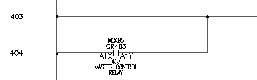
Select component, wire, or wire number for SCOOT:
Select the component that was inserted at line reference 403
The cursor changes to a box.
Select component, wire, or wire number for SCOOT: to
Move the cursor to the right and click, right-click to exit the command
The component moves to its new location.
You can use the Scoot tool to grab a component or a wire number and slide it back and forth along a wire. You can grab a wire or a whole rung of circuitry and scoot it to a new position, while keeping everything connected.
The steps to insert a parent component and a child component are the same, except when you annotate the symbol.
Insert a child component
- Click
. Find
- In the Insert Component: JIC Schematic Symbols dialog box, click Relays/ Contacts.

- In the JIC: Relays and Contacts dialog box, click Relay NO Contact.

- Respond to the prompts as follows:
Specify insertion point:
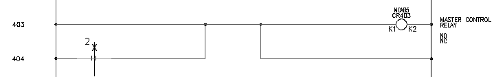
Position the cursor on the wire at line reference 404 near the hot wire and click (1)
The Insert/Edit Child Component dialog box displays. Notice that AutoCAD Electrical toolset did not automatically assign a tag name for the relay contact; there is just a generic “CR” in the edit box. Determine the relay contact tag name. A relay contact is a child component that must link to a parent relay coil on a drawing in the active project. The child gets the same tag name that is found on the parent relay coil.
Assign the tag name by clicking Parent/Sibling and picking the parent in the drawing. Or, click Drawing or Project to select from a list of components with the same family name.
- In the Insert/Edit Child Component dialog box, Component Tag section, click Drawing.
- In the Active Drawing list for FAMILY=”CR” dialog box, select:
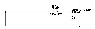
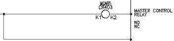
MCAB5 CR403 MASTER CONTROL RELAY
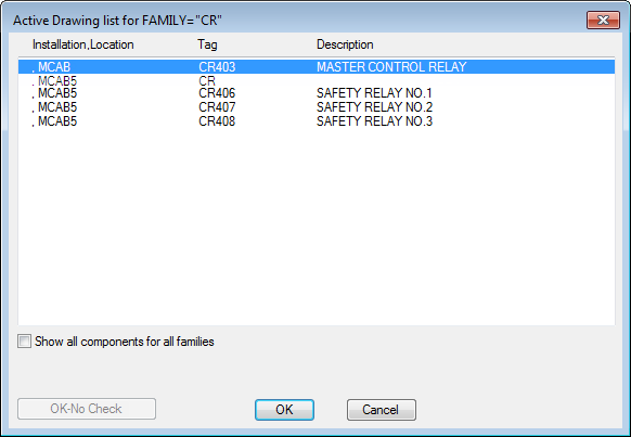
- Click OK.
The values of the parent are immediately transferred to the contact.
- In the Insert/Edit Child Component dialog box, verify that the following options are specified:
Component Tag: CR403
Description: Line 1: MASTER CONTROL
Description: Line 2: RELAY
Cross-reference: 403
Location code: MCAB5
Pins: Pin 1: A1X
Pins: Pin 2: A1Y
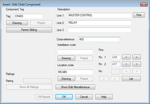
- In the Insert/Edit Child Component dialog box, click OK.
The child component is inserted. It is cross-referenced in real time. The coil is annotated with the line reference number of the new child contact. The child contact gets annotated with the line reference location of the parent coil.