Use Circuit Builder to insert and configure a 3-phase motor circuit.
You now construct a new motor circuit on the extended 3-phase bus.
Insert and configure the circuit
- Click
 . Find
- The Circuit Selection dialog box displays.
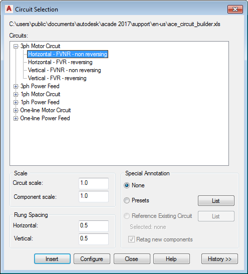
- Expand 3ph Motor Circuit.
- Select Horizontal - FVNR - non reversing.
- Change the Rung Spacing: Horizontal to 0.5.
- Select Configure.
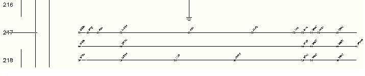
- Specify insertion point at rung 217.
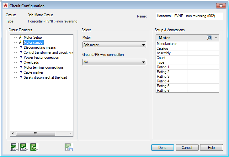
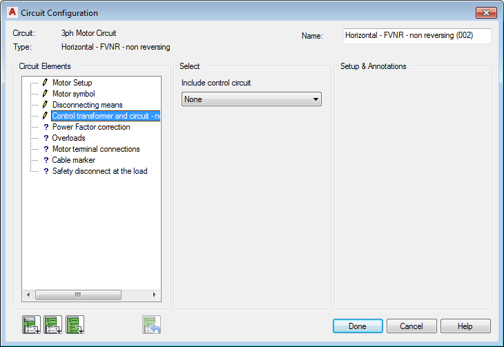
Circuit Configuration
- In the Circuit Elements section, select
Motor symbol.
In the Select section, select Motor: 3ph motor,
Ground/PE wire connection: No.
- In the Circuit Elements section, select
Disconnecting Means.
In the Select section, select Main Disconnect: Fuses,
Include N.O. auxiliary contact: No.
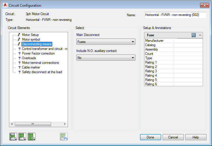
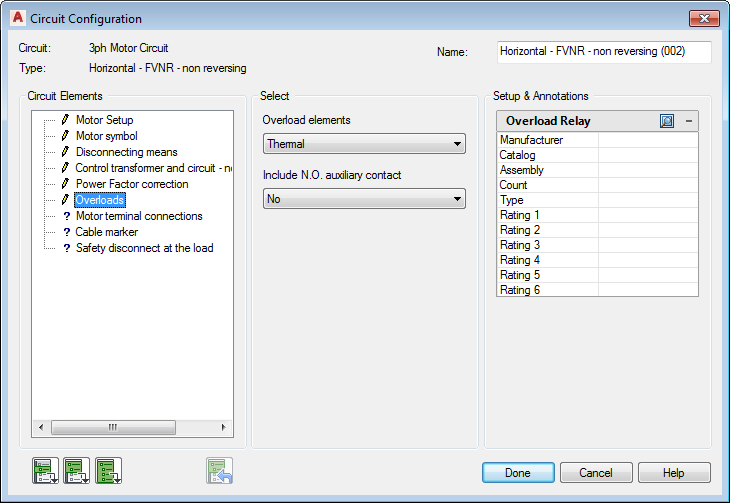
Setup & Annotation section: The options within this section change according to your selections in the Circuit Elements and Select sections. Type in values or select the Browse button to access a lookup table.

Select an entry from the lookup table to obtain values for the individual settings. If the circuit option is a component, the catalog lookup opens.
- In the Circuit Elements section, select
Control transformer and circuit - non-reversing.
In the Select section, select Include control circuit: None.
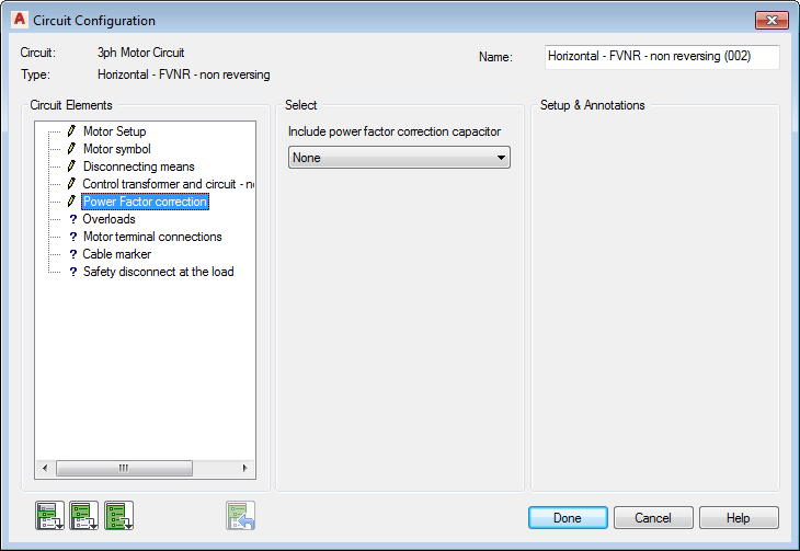
- In the Circuit Elements section, select
Power Factor correction.
In the Select section, select Include power factor correction capacitor: None.
- In the Circuit Elements section, select
Overloads.
In the Select section, select Overload elements: Thermal,
Include N.O. auxiliary contact: No.
- In the Circuit Elements section, select
Motor terminal connections.
In the Select section, select Motor connection terminals: Round.

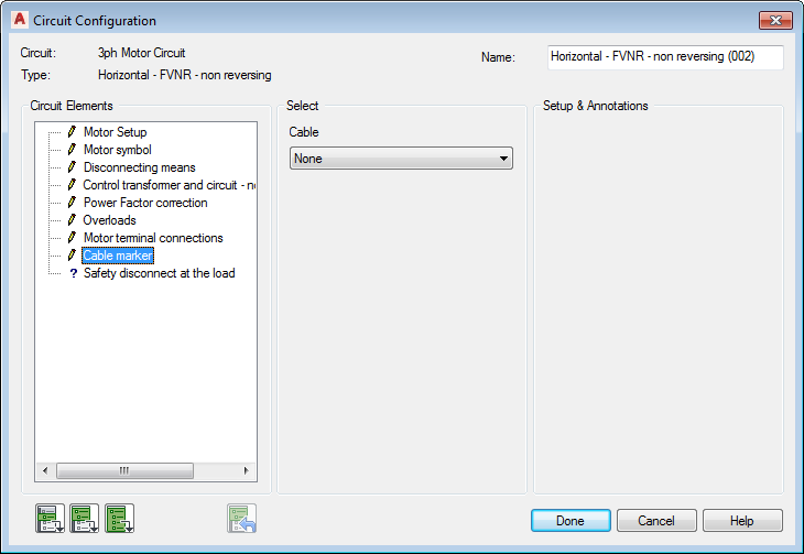
- In the Circuit Elements section, select
Cable marker.
In the Select section, select Cable: None.
- In the Circuit Elements section, select
Safety disconnect at the load.
In the Select section, select Safety disconnect: Disconnect switch,
Include N.O. auxiliary contact: No.
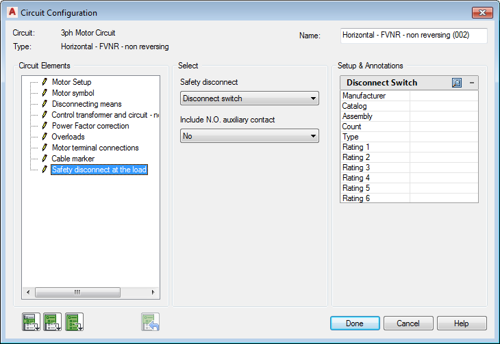
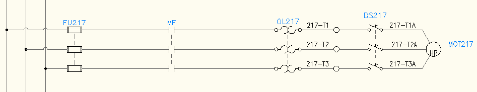
- Select the Insert all circuit elements tool. Circuit Builder inserts each of the selected circuit elements.

- Select Done.
A circuit is made up of individual circuit elements and the wiring that connects them. Circuit Builder inserts a template drawing. This template contains the base wiring for the circuit and strategically positioned “marker blocks”.
The “marker blocks” control what circuit elements are presented in the Circuit Configuration dialog box. For example, a “marker block” indicates the need for a Disconnecting Means in the circuit. Various options for the Disconnecting Means are presented in the dialog box. The option selected for this circuit element is inserted at the location of the “marker block”. Circuit Builder dynamically builds the complete circuit based on the selections you make on this dialog box.