Move a circuit to a new location and update all related components.
When you move a circuit, most of the parent components contained in the circuit automatically retag since the drawing is set up for reference-based component tagging. In the process of moving the circuit, you change the reference locations of the moved components. Related child components update to match the new parent tags, including references on other drawings in the project.
Move the location of a circuit
- If AEGS is not the active project, in the Project Manager, right-click AEGS and select Activate.
- In the Project Manager, double-click AEGS to expand the drawing list.
- In the Project Manager, Project Drawing List, double-click AEGS02.dwg.
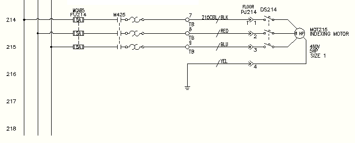
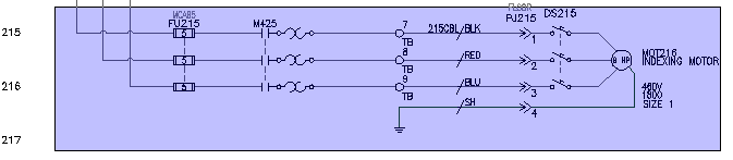
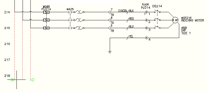
- Zoom in on the lower left corner of the drawing. Make sure the 3-phase motor circuit at line reference 215 is visible.
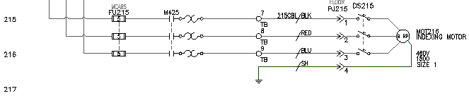
This circuit has component tags
- “FU215” on the 3-pole fuse
- “215CBL” on the multi-conductor cable
- “DS215” on the disconnect switch
- “MOT216” on the motor
- Click
 . Find
- Respond to the prompts as follows:
Select Objects:
Window select the circuit on line reference 215 to capture the connection wire and dots that tie in to the vertical bus, right-click
Press F9 to turn on SNAP .
Specify base point or displacement:
Select a base point and then select a point on line reference 214
The circuitry is moved, the affected components are retagged, and cross-references are updated based on the new line reference. Each of the listed parent component tags decrement by one. For example, fuse FU215 became FU214.
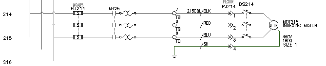
- In the Update Related Components dialog box, click Yes-Update.
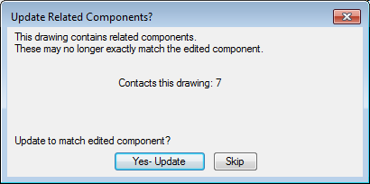
Related child references on the active drawing update to match the newly retagged parent components.
- In the Update other drawings dialog box, click OK.
Related child components and panel layout references on other drawings update to match the parent components on the moved circuit.
- If asked to save the drawing, click OK.
- Click
. Find
- Select FU214 on the drawing.
The Surf dialog box displays three references on sheet 2 and one reference on sheet 9.
- Double-click the reference on Sheet 9.
Surfer goes to the panel layout drawing and zooms in on the physical representation of this 3-pole fuse. Notice that the physical representation of the fuse block tag updated because the circuit was moved.
- Double-click the first entry in the dialog box to return to the original AEGS02.dwg drawing.
- Click Close.
Moving the motor circuit up one line reference spacing opened up a bit more room to add a new circuit below it. The next step is to extend the 3‑phase bus down to line reference 218 and over to the right to begin building a new motor circuit.
Extending the 3-phase bus
- Click
. Find
- Respond to the prompts as follows:
Fence/Crossing/Zext/<Select wire to TRIM>:
Click the bottom ends of the three dangling wires, right-click
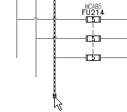
You can insert vertical or horizontal 3-phase wiring. Three-phase wiring automatically breaks and reconnects to any underlying components that it finds in its path. If it crosses any existing wiring, wire-crossing gaps are inserted.
- Click
. Find
- In the Multiple Wire Bus dialog box, select:
Horizontal Spacing: 0.5
Vertical Spacing: 0.5
Starting at: Another Bus (Multiple Wires)
Number of Wires: 3
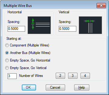
- Click OK.
- Respond to the prompts as follows:
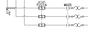
Select existing wire to begin multi-phase bus connection:
Select the bottom corner of the left-most vertical bus on line reference 214 as shown
Select existing wire to begin multi-phase bus connection: to
Pull the cursor down to line reference 218.
Temporary graphics show the proposed routing of the extended bus.
- Click to create the wires.
- Right-click to exit the command.
The 3-phase bus and wire connection dot symbols are inserted on the drawing.