Use the AutoCAD Electrical toolset Tagging and Linking tools to associate non blocked text to panel components.
The AutoCAD Electrical toolset Tagging and Linking tools work on panel components the same way they work on schematic components.
Tag and link panel components
- Open Convert-04.dwg.
- Zoom in on the components in the middle of the drawing.
- Click
 . Find
- Respond to the prompts as follows:
Select objects:
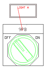
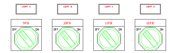
Select push button lights A - D (including all graphics and text) (use either single picks or window-select), right-click
The blocks explode into separate text entities and geometry.
The Tag Panel Component tool makes selected text entities an attributed block file with the P_TAG1 attribute visible. The template block file (ACE_P_TAG1_CONVERT.DWG) contains attributes for a panel component.
- Click
. Find
- Respond to the prompts as follows:
Select objects: Select 9PB, 10PB, 11PB, and 12 PB, right-click
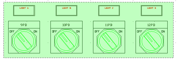
Note: You may have to right-click several times to exit the command.The text changes color to indicate that it has been tagged. The color of the PTAG attribute is by layer. The attribute is the same layer as defined on the WD_M block.
- Click
. Find
- Respond to the prompts as follows:
Select objects: Select 9PB, right-click
Select text to fill in next available DESC attribute:
Select LIGHT A, right-click
Note: You may have to right-click several times to exit the command.