Insert a connector across existing wires.
Now that you wired the connectors together, you insert in-line connectors to group the wires.
Insert in-line connectors
- Click
 . Find
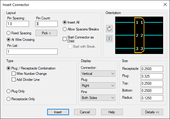
- On the Insert Connector dialog box, specify:
Pin Spacing: 1.0
Pin Count: 3
At Wire Crossing
Pin List: 1
Insert All
- Click Details.
- On the Type section, clear the Add Divider Line box.
- On the Display section, set Plug to Right and Pins to Both Sides.
- On the Size section, set the Plug to 0.325.
- Click Insert.
- Respond to the prompts as follows:
Specify insertion point or [Z=zoom, P=pan, X=wire crossing, V=horizontal/vertical, TAB=flip]:
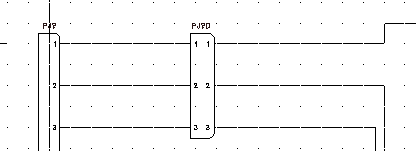
Select to place the connector on the wires connected to PJ1, Pins 1-3
- Click
. Find
- On the Insert Connector dialog box, specify:
Pin Spacing: 1.0
Pin Count: 9
At Wire Crossing
Pin List: 1
Allow Spacers/Breaks
- Click Insert.
- Respond to the prompts as follows:
Specify insertion point or [Z=zoom, P=pan, X=wire crossing, V=horizontal/vertical, TAB=flip]:
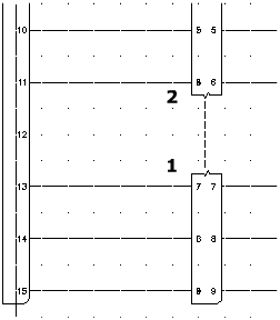
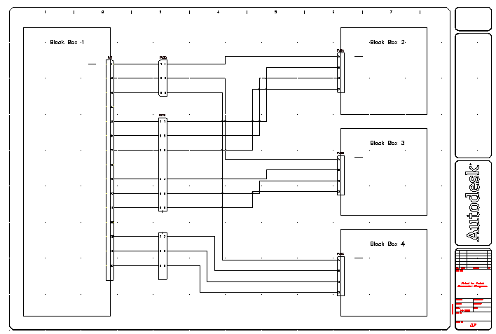
Select to place the connector starting on the line at PJ1, Pin 5
Notice how the connector expands when you cross the wires.
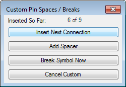
- On the Custom Pin Spaces/Breaks dialog box, click Insert Next Connection.
The dialog box displays which connector pin has been inserted so far. Keep clicking Insert Next Connection until you place six of the nine connections.
- When the Custom Pin Spaces/Breaks dialog box says “Inserted So Far: 6 of 9,” click Break Symbol Now.
- Respond to the prompts as follows:
Specify insertion point or [Z=zoom, P=pan, X=wire crossing, V=horizontal/vertical, TAB=flip]:
Select to place the connector starting on the line at PJ1, Pin 13
- On the Connector Layout dialog box, select Insert All.
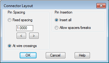
- Click OK.
 Note: Another method is to insert the entire connector and then use the Split Connector tool to break the existing connector.
 - Click
. Find
- Respond to the prompts as follows:
Component to link from: Select the bottom portion of PJ6 (1)
component to link to: Select the top portion of PJ6 (2), right-click