Process and tag wires on the current drawing, wires in the project, or individually picked wires. Insert special wire numbering associated with 3-phase bus and motor circuits.
Insert Wire Numbers
- Click
 . Find
- Select to tag all wires or only new wires.
- Select to process and tag wires with sequential wire numbers or with wire numbers based on the line reference location of the wire network.
- (Optional) Set other tagging options such as:
- specify the wire tag format to use
- specify the wire layer format
- force all wire numbers to be fixed
- update cross-reference text on wire signal source and destination symbols
- update the database for wire signal source and destination symbols
- Select to tag the selected wires, wires on a drawing, or wires in a project.
Sequential Wire Numbering
You can force new incremental wire numbers (as opposed to line referenced numbers) to increment by more than one during insertion.
- Click
. Find
- Click the Wire Numbers tab.
- In the Wire Number Format section, select Sequential and set the increment value.
- (Optional) For this increment value to be your standard for all new drawings, follow the same procedure in the Project Properties Wire Numbers dialog box.
- Run the Wire Numbers command.
Insert Special Wire Numbering
- Click
. Find
- Enter a base starting number in the edit box or click Pick to select an existing attribute value on the active drawing.
If the picked text carries a numeric substring, it is extracted and inserted into the Base edit box.
- Enter an optional Prefix and/or Suffix value or choose from a default pick list by clicking List.
The prefix or suffix value can be a comma-delimited string with each entry applied in sequence to the Wire Numbers section. The section is at the right-hand side of the dialog box.
- Set the hold and increment options for each of the edit box values as required. Pay attention to the proposed generated wire numbers in the right-hand side of the dialog box.
- Set the number of wire numbers needed in the bottom right-hand side of the dialog box.
Tip: Select None to generate a continuous list of incrementing wire numbers.
- Select OK.
- Select the wires for the wire numbers, either single picks or using the Fence selection.
Fence selection inserts the wire numbers at the crossing points while single selections use the default wire number placement of the drawing. (For example, centered on the wire segment.)
Tips and Hints
- Tab out of an edit box to start the Wire Numbers listing to update.
- You can add to the default prefix and suffix list display. Create an ASCII text file and list each prefix/suffix entry, one per line in the file. Name the file <projectname>.3ph (where "projectname" is the name of your active project) or default.3ph and put the file in any folder that is part of the search path list in AutoCAD Electrical toolset.
- The wire number assignments go in as Fixed.They hold the values that you have assigned and do not retag with a subsequent run of the Insert Wire Numbers command).
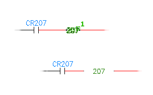
Copy Wire Numbers
A copy of a wire number follows the main wire number of a network. You can position the copy anywhere on a wire network. If AutoCAD Electrical toolset modifies a main wire number, the copies of the wire number update as well. Extra wire numbers go on the Wire Copies layer defined in the drawing properties.
- Click
. Find
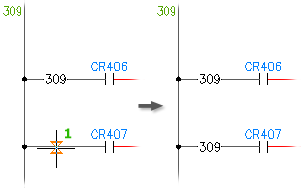
- Select the wire location where you want the extra wire number to insert.
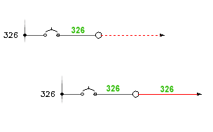
Copy Wire Numbers In-line With the Wire
Inserts an extra copy of a wire number in-line at a pick point.
Positions wire numbers in-line with the wire rather than above or below the wire.
- Click
. Find
- Specify the insertion point for the wire number.
- If there is no wire number, enter the wire number in the Edit Wire Number/Attributes dialog box. Use Pick Text to select similar text from the drawing, or click the arrows to increment or decrement the wire number.
- Click OK. The wire number is automatically inserted in-line with the wire.
If the gap between the wire and the wire number text is not large enough you can change the gap setup.
- Click
. Find
- Type S and press Enter to open the In-Line Wire Label Gap Setup dialog box.
- Adjust the values as necessary to define the adjustment for the gap size.
- A: Specifies the width between the end of the wire and the text. The second option for setting "A" is the snap setting for the width. The width stays constant until the text grows to a point where the Text + A + A gets past the current gap width in the wire. The gap width then jumps up to the next snap width increment. If this second value is set to 0.25, the gaps in the wires are always going to be at 0.25 increments (0.25, 0.5, 0.75, 1.0). If this middle value is left at 0.0, then the snap distance is 0 and the gap in the wire grows or shrinks smoothly as the wire text grows or shrinks.
- C: Specifies the minimum gap width by setting a fixed size value. If you want fixed spacing for the in-line wire number gap, enter a size value in the C edit box. A non-blank C value gives the minimum gap width even if the wire number is a single character or was blanked out.
The gap is adjusted for the selected wire number.