When you configure a display configuration, you can specify the cut plane and display ranges. In the plan view, AutoCAD MEP 2023 toolset uses the cut plane settings for the current display configuration. It also uses the elevation of an object to determine which display component (Below, Low, High, or Above) is used to display the object.
To set cut plane and display ranges
- Select Enable Display by Elevation in the Options dialog box.
- Specify the cut plane settings using one of the following methods:
If you want to... Then... define the cut plane height for the current display configuration click the Cut Plane value on the status bar. define the cut plane height for any display configuration Click
 .
.  Select a display configuration that uses a Plan display representation in Top (plan) view or a 1 Line (for Duct domain only). Click the Cut Plane tab in the right pane.
 - For Cut Height, enter a value for the cut plane.
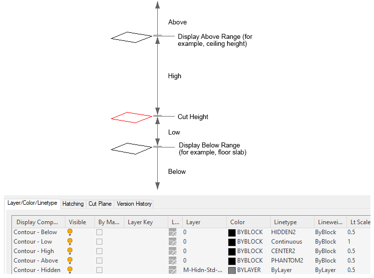
The cut plane is the height at which an object is cut to produce the plan representation.
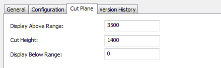
Example of Cut plane tab in the Display Manager
The values you enter for the Above and Below ranges are not relative to the cut height. They are absolute height values calculated from the WCS origin. Therefore, the value that you enter for Display Above Range must be greater than the value that you enter for Cut Height. Invalid values will produce incorrect results.
Note: The Calculate button on the Cut Plane tab is only available if you selected a project using Project Navigator and the current drawing is multi-story. It opens a Cut Plane dialog box that you use to set the cut plane height for objects at a specific level. - For Display Above Range, enter a value for the top range of the floor plan.
Objects above this range are displayed using the Above display components. For example, in 1-line display representations, this is the Single Line - Above component. In plan display representations, these are the Contour - Above, Insulation - Above, and Rise Drop - Above components.
Objects at or below this range, but above the cut height, are displayed using the High display components.
- For Display Below Range, enter a value for the bottom range of the floor plan. Objects at or below the cut plane, but above this height, are displayed using the Low display components. Objects at or below this height are displayed using the Below display components.