You can draw parallel conduit runs, where bend radius values are automatically calculated as you make turns. Use this procedure to draw parallel routing for a conduit system.
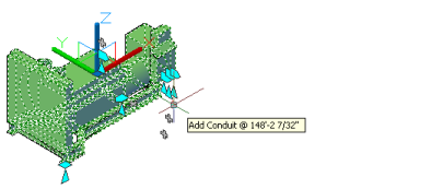
- Add equipment to your drawing. Select the MvPart, and click
 (Add grip).
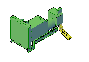
Generator MvPart
- Add conduit to the layout.

- Continue to add more conduit segments (using
 on the MvPart).
- To start parallel routing, click


 .
.  Tip: You can also enter ParallelRouting at the command line.
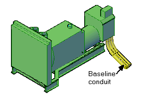
 - Select the baseline conduit.
 Tip: Routing begins at the open end of the baseline conduit segment. If the segment is open at both ends, click near the end where you want the routing to begin.
 - Select the parallel conduit segments and press Enter.

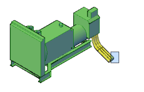
- Select the next points in the run.
As parallel segments are drawn, each segment is created according to the routing preferences and properties specified for the baseline conduit segment. A constant distance is maintained between the segments where possible.

Drawing segments along the run
By default (as shown next), the correct radius is calculated for inside, middle, and outside radius values in each conduit bend. You can adjust Radius of curvature on the Properties palette at any time after the conduit runs are laid out.

Completed run
You can change the parallel bend type on the Properties palette from Concentric (default) to Fixed radius, when in parallel routing mode. With fixed radius, elbows in the conduit run use their predefined radius values and are not adjusted. For more information, see Specifying Parallel Bends in the Conduit Run.
Note: If the routing preference for one or more segments does not specify a required conduit type or fitting or if a discrepancy exists, the Choose a Part dialog box prompts you to specify a different part. See Choosing a Part for more information.