Basic properties reflect the default or the last stored value. When multiple objects are selected in the drawing, not all properties appear in the Properties palette. Those that do appear are designated with asterisk(s) as follows:
- * Appears when multiple conduit segments are selected
- ** Appears when multiple fittings are selected
- *** Appears when either multiple conduit segments or multiple conduit segments with fittings are selected
| General | Description | Conduit | Fitting | Add | Modify |
|---|---|---|---|---|---|
|
Description* |
Describes the part |
|
|
|
|
| Layer* | Specifies a layer style |
|
|
|
|
| System* | Specifies the system definition |
|
|
|
|
| Part | Designates the part. Click the image to display the Select a Part dialog box. |
|
|
|
|
| Current size | Specifies the fitting size |
|
|
|
| Dimensions | Description | Conduit | Fitting | Add | Modify |
|---|---|---|---|---|---|
| Connections | Displays the nominal diameter for each conduit connector |
|
|
|
|
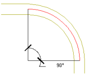
| Path angle | Specifies an angle value that represents the arc's scanning path. Angle values are stored in the catalog content and vary depending on the type of conduit fitting:
 90° path angle |
|
|
|
|
| Radius of curvature | Specifies a radius dimension for the part based on the industry standard. The values originate from the conduit catalog content and vary depending on the part’s nominal size. |
|
|
|
|
| Part | Specifies the fitting part |
|
|
||
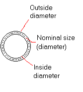
| Nominal size* | Specifies the dimension, based on the outside and inside diameters of the conduit (as shown). Nominal size (also referred to as trade size) complies with industry standards.  |
|
(Modify only) |
|
|
|
Size |
Prevents changing the nominal size |
|
(Modify only) |
|
|
| Routing preferences* | Used to draw accurate runs in auto layout (based on the connection type) Note: For more information, see Conduit Routing Preferences.
|
|
(Modify only) |
|
|
| Specify cut length | Allows breaking of conduit segments. If Yes is selected, see Cut length (below). |
|
|
||
| Cut length | If Yes is selected (above), specifies the cut length for each segment. |
|
|
|
| Placement | Description | Conduit | Fitting | Add | Modify |
|---|---|---|---|---|---|
| Elevation* | Specifies the elevation above or below the XY plane of the object |
|
|
|
|
|
Elevation |
Prevents a segment at 1 elevation from snapping to a segment at another |
|
|
|
|
| Start elevation | Specifies the elevation at the start of the segment (equal to elevation) |
|
|
|
|
| End elevation | Specifies the elevation at the end of the segment |
|
|
||
| Move attached segments* | Maintains connectivity if the selected part’s elevation changes |
|
|
|
|
|
Additional information*** |
Displays the Location worksheet (connector 1 details); changes made affect all connectors on the object |
|
|
|
|
| Specify rotation on screen | Allows a fitting to be rotated in drawing. If No is selected, see Rotation (below). |
|
|
||
| Rotation** | If No is selected (above), specifies the fitting routing angle. |
|
|
|
|
| Justify | Specifies the justification setting for a conduit segment Remember: For more information, see Justification of Objects.
|
|
|
||
| Horizontal/Vertical offset | Specifies the placement offsets in the applicable direction from the insertion point |
|
|
| Routing Options | Description | Conduit | Fitting | Add | Modify |
|---|---|---|---|---|---|
| Parallel bends |
Specifies the type of bend radius to use for parallel conduit routing. This option is only available when drawing parallel conduit runs. Selections include Concentric or Fixed radius. See below.  Concentric  Fixed radius Remember: See Specifying Parallel Bends in the Conduit Run.
|
|
|
||
| Slope format | Specifies how the slope is represented (such as angle, percentage, rise/run). This property is also available in the Conduit Layout Preferences dialog box. |
|
|
|
|
| Slope | Specifies the pitch of the drawn segment |
|
|
||
| Bend angle | Specifies the angle by which the routing is constrained (derived from the catalog). This property was formerly called elbow angle. |
|
|
||
| Bend angle |
Prevents the editing of the bend angle in auto layout |
|
|
||
| Bend radius | Specifies the radius of curvature to the conduit bend. |
|
|
||
|
Bend radius |
Prevents the editing of the bend angle in auto layout |
|
|