You can use justification on the Properties palette to offset a new pipe run from an existing run. When you draw the parallel run, you select points on the existing run, and the new parallel run is created at the offset distance. You can select points on the existing run using AutoCAD MEP 2023 toolset snaps.
Tip: Drawing a parallel pipe run might be easier if you use a 1-line display for the existing pipe run. This reduces the potential number of points to specify, and it allows you to accurately select transition points.
To draw a parallel pipe run using offsets
- Verify that the AutoCAD MEP 2023 toolset pipe snaps are turned on, and turn off
 (Object Snap) and
  (Object Snap Tracking) on the application status bar.
 - Add pipe, as explained in Creating a Piping System.
- On the Properties palette, under Justification, specify the horizontal and vertical offsets:
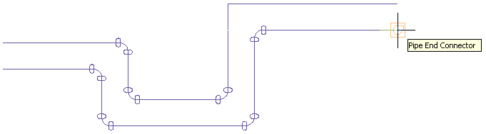
If you want to then offset the new run at a horizontal distance (X or Y direction) from the existing run, with both runs at the same elevation under Justification, set a value for Horizontal offset. To offset the new run in a positive X or Y direction from the existing run, enter a positive value. To offset in a negative X or Y direction, enter a negative value. offset the new run at a vertical distance from the existing run, with both runs having the same X-Y dimensions at different elevations under Justification, set a value for Vertical offset. To offset the new run in a positive Z direction from the existing run, enter a positive value. To offset in a negative Z direction, enter a negative value. - In the drawing, select the pipe end connector at the start of the existing pipe run.
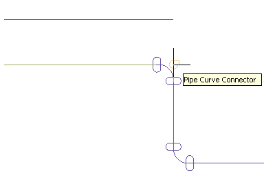
- Continue selecting points along the run. Attention: To achieve the most accurate layout, select points at each end of the pipe segments. For angled transitions, such as elbows, select only the pipe curve connector at the logical intersection of the fitting centerlines as shown in the following example.
Note that for elbows and other curved fittings, a pipe curve connector is displayed at the logical intersection of the fitting centerlines. This ensures that the pipe is offset the specific distance along the entire parallel run.
Attention: If you draw parallel pipe runs close to each other and plot them at a small scale, they may blend together on the plotted sheet. In the drawing, you may need to space the pipe runs far enough apart so that they render accurately and individually on the plot.