- In the Schematic workspace, start the add command by doing one of the following:
- Open a schematic tool palette, and select a schematic line tool.
If necessary, scroll to display the tool. Because tools contain preconfigured properties for the objects they create, you might not need or be able to specify some of the schematic line properties referenced in this procedure.
-
Click

 .
.
- Enter slineadd.
Note: On the Properties palette, indicates a property is available only when you are adding schematic lines, not when you are modifying them.
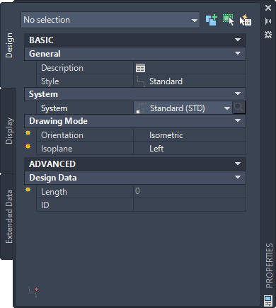
- Open a schematic tool palette, and select a schematic line tool.
- Expand Basic, and for Description, click
 , enter a description for the schematic line, and click OK.
 - For Style, select a schematic line style.
You can select from the styles in the current drawing.
- For System, select the system to which the schematic line belongs.
You can select from the systems in the current drawing.
Tip: You can create schematic line tools that reference styles and systems in content libraries (DWG files). - For Orientation, select Isometric.
- For Isoplane, select the isoplane on which to start drawing: Left, Top, or Right.
- Expand Advanced, and for ID, select or enter an identification label.
The schematic line style that you select determines the list of available IDs. You can select an ID from the list or enter a different one.
- In the drawing, specify the start point for the line, or use schematic AutoCAD MEP 2023 toolset snaps to connect the line to a symbol or another line.
- Continue to specify points to draw the schematic line.
- To change isoplanes as you draw, on the Properties palette, select a different isoplane for Isoplane, and then continue to specify points to draw the line.
The UCS icon and crosshairs adjust to the selected isoplane.
- If necessary, on the Properties palette, modify the schematic line properties and add additional lines.
- Press ENTER to end the add command.
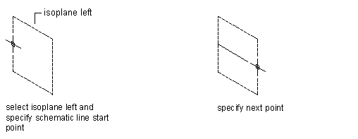
Drawing a schematic line on the left isoplane
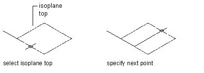
Drawing a schematic line on the top isometric plane
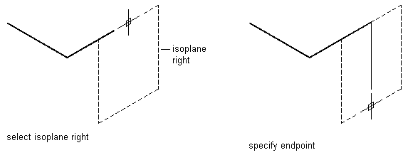
Drawing a schematic line on the right isometric plane
Tip: You can quickly connect existing schematic lines by extending or trimming them using the AutoCAD FILLET command.