Define elevation, offset, and surface target parameters for the subassembly.
You can rearrange (by dragging and dropping) the order of the input/output parameters and target parameters of the subassembly on the Input/Output Parameters tab or the Target Parameters tab. Click the parameter name and drag it up or down in the order of parameters.
To create a target parameter, click Create Input Parameter.
Use the table to define the parameter:
| Name | Specifies a name for the target parameter. The name must not start with a numeral or contain spaces or special characters. |
| Type | Specifies the target parameter:
|
| Preview Value | Specifies where the target parameter is drawn in the Preview panel, relative to the point of origin. |
| Display Name | Specifies the parameter name, as it appears in the Autodesk Civil 3D Properties palette. The Display name must not begin with a numeral. |
| Enabled In Preview | Specifies that the target parameter is enabled in the preview panel. Clear the check box to test how the subassembly will react when the specified target is not found.
Note: Set the preview panel to Roadway Mode to view this effect.
Note: This is useful for testing a subassembly that has an
IsValid function applied to it. Clearing this check box shows you how the subassembly will react when the target is not found.
|
Example
To see an example of an subassembly that uses the IsValid function with an offset target, open the following Sample PKT file:
IsValid_Example.pkt
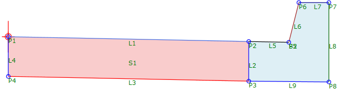
This example shows a lane and a curb and gutter. The curb and gutter portion is defined in a sequence named Curb. The subassembly is defined so that the Curb sequence is only applied if an offset target is found.
This subassembly has a decision defined for it with the condition OffsetTarget.IsValid. If the offset target is found, then the Curb sequence is applied. If the offset target is not found, then the Curb sequence is not applied and the lane is drawn using the width that is defined in the subassembly (which is the Delta X value defined for P2). An input parameter is also defined for the lane width so the lane width can be modified when the subassembly is used in Autodesk Civil 3D.
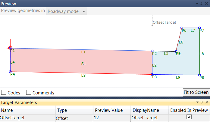
The subassembly also has an OffsetTarget parameter defined for it on the Target Parameters tab. When the preview panel is set to Roadway Mode, you can view how the subassembly will react if the offset target is found by selecting the Enabled In Preview check box, as shown in the following illustration.
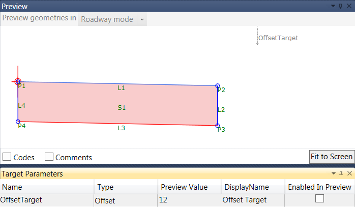
You can clear the Enabled In Preview check box to view how the subassembly will react if the offset target is not found, as shown in the following illustration. In this case, the lane width is changed to use the width defined in the subassembly.
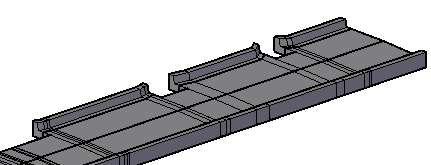
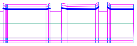
The following illustration shows a portion of a corridor that was created with this subassembly in Autodesk Civil 3D. The dark blue lines represent the offset targets. Where the offset target is not found, the curb and gutter portion of the subassembly is not applied.
The following illustration shows a 3D view of a portion of the corridor after using the Extract Corridor Solids command in Autodesk Civil 3D.