Decision
Specify two geometry options, the application of which depends on a specified condition. Decisions can use conditions such as true/false, yes/no, and cut/fill.
A decision enables you to specify a condition, and then define a True branch and a False branch in the flowchart:
- If the specified condition is met, the geometry in the True branch is drawn.
- If the specified condition is not met, the geometry in the False branch is drawn.
Properties
Specify the following parameters in the Properties panel.
| Miscellaneous | |
| Condition | Defines the condition. Click [...] to open the Expression Editor, where you can enter or calculate a value. |
| False Label | Specifies a label to display in the flowchart for the False geometry branch. |
| True Label | Specifies a label to display in the flowchart for the True geometry branch. |
Example: Yes/No
To see an example of how this geometry element is used to reflect an input parameter setting, open the following Sample PKT file:
Decision Yes No Example.pkt
In this example, a shape is drawn when the DrawShape input parameter is set to Yes.
Example: Cut or Fill Condition
To see an example of how this geometry element is used for a cut or fill condition, open the following Sample PKT file:
Decision Cut or Fill Example.pkt
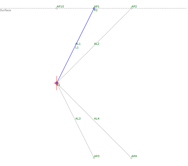
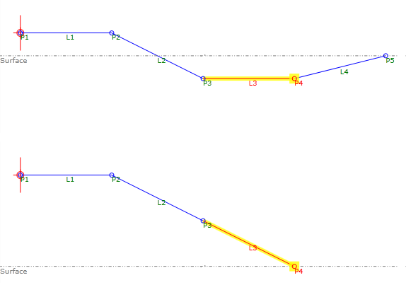
In this example, an Auxiliary Point is used to obtain the elevation of the target surface. The Y value of P3 relative to the Y value of AP1 surface determines the geometry:
- When the distance between P3 and the surface is less than 0 (a cut condition), a ditch is created before sloping up to the surface.
- When the distance between P3 and the surface is greater than 0 (a fill condition), it draws a link that slopes to the surface at the same slope as L2.
Example: Range of Values
To see an example of how to use a series of decisions to accommodate a range of values, open the following Sample PKT file:
Decision Range Example.pkt
In this example, an Auxiliary Point is used to obtain the distance between P1 and the target surface. First, the distance determines whether P1 is in a Cut or Fill condition. Next, decisions are used under the Cut and Fill branches to determine the height of the fill, or the depth of the cut. Finally, P2 and L1 are drawn at the slope that has been specified for the condition.