Loop Geometry
Repeats specified links until they reach a Surface Target or until they are repeated a specified number of times.
Design and Usage Considerations
You can attach another subassembly to a subassembly that contains loop geometry when the loop repetition is determined by a constant value or by an Input/Output parameter.
However, when the loop repetition is dynamically determined by a Surface Target, the location of any other subsequent subassembly that is attached to a subassembly that contains loop geometry may be uncertain (since the point to which subsequent subassembly is attached may change or may not exist in Roadway Mode due to the surface condition). Therefore, when the loop repetition is dynamically determined by a Surface Target, you must add all subsequent subassembly geometry to the same PKT file that contains the loop geometry.
Properties
Specify the following parameters in the Properties panel.
| Loop | |
| Loop Number | Specifies the number of the loop. You can change the automatically generated Loop Number value. |
| Loop Repetition | Specifies the maximum number of times the loop geometry repeats. You can enter a value in the Loop Repetition field or you can create an Input/Output Parameter to control the repetition and enter that parameter in the Loop Repetition field. Note: To create a repetition parameter on the Input/Output Parameter tab, use Integer as the Type.
|
| Source Geometry | |
| Links | Specifies which links to include in the loop geometry. |
| Loop Condition | |
| Surface Target | Specifies the target surface. Note: The surface must be defined as a Target Parameter in order to specify it as a Surface Target.
|
| Miscellaneous | |
| Comment | Indicates notes about the loop geometry. Comments can be displayed in the Preview panel. |
Example
To see an example of loop geometry, open the following Sample PKT file:
Loop_Geometry_Example.pkt
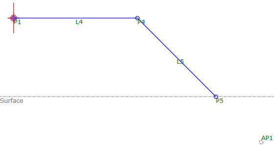
This example is designed to work in a fill situation and uses loop geometry (created from L1 and L2) to create benching.
The loop geometry has a Surface Target defined. When the Surface Target in the sample PKT file has a Preview Value of -45, the loop geometry repeats three times, and then additional links (L3 and L5) are inserted to create a partial bench that meets the surface (as shown in the illustration above). You can adjust the Preview Value of the Surface Target for the sample PKT to see how the repetition changes when the PKT encounters different surface values.
The loop repetition for this PKT is specified as 10, so it will repeat up to a maximum of 10 times. If the loop geometry repeats to its maximum number of 10 times and has not yet reached the Surface Target, then L5 will extend to the surface.
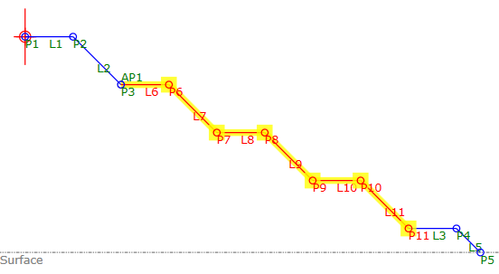
A decision has been added to the PKT file to determine whether a partial bench (used when the decision result is True) or a full bench (used when the decision result is False) is required. Auxiliary point AP1 is used to test for the condition of this decision.
The partial bench geometry, shown in the following illustration, is used if the distance to the surface is not great enough for a full bench to be used.