To define superelevation for a subassembly, use the Input/Output Parameters tab to add both Superelevation Axis of Rotation and Superelevation parameter types. After you select the ApplyAOR check box in the Properties panel for links to which you want to apply superelevation, you will see the superelevation effect in the Preview panel in Roadway Mode. Use the Superelevation tab to define how superelevation slopes are represented in the Preview panel.
The ApplyAOR check box affects how the subassembly is previewed in the Subassembly Composer and how the subassembly behaves when it is used in Autodesk Civil 3D.
You can adjust the values of the superelevation parameters that you define on the Input/Output Parameters tab after you import the subassembly into Autodesk Civil 3D. After you have added the correct lane subassembly which is applicable to the corridor superelevation setting, the superelevation effect is visible in the corridor section view.
Examples
To see examples of how superelevation is defined, open the following Sample PKT files:
Superelevation_Example_1.pkt
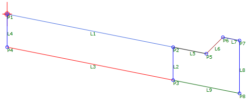
This example shows a lane and a curb and gutter.
- ApplyAOR is specified for L1, L3, L5, L7, and L9.
- Superelevation parameters are specified on the Input/Output Parameters tab.
- Values to show in the Preview panel are specified on the Superelevation tab.
Superelevation_Example_2.pkt
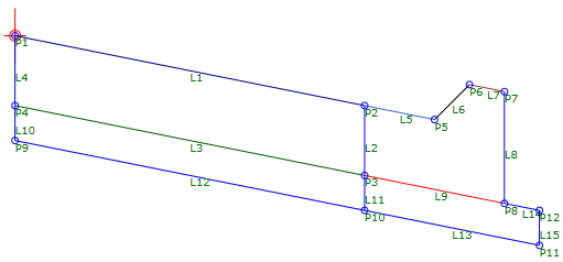
This example shows a lane, a curb and gutter, and a base.
- ApplyAOR is specified for L1, L3, L12, L5, L7, L9, L13, and L14.
- Superelevation parameters are specified on the Input/Output Parameters tab.
- Values to show in the Preview panel are specified on the Superelevation tab.