Link
Link
Use links to connect two sequential or non-sequential points with a straight line.
Properties
Specify the following parameters in the Properties panel.
| Link | |
| Link Number | Specifies the link number. You can change the automatically generated Link Number value. |
| Link Codes | Specifies the codes assigned to the link. |
|
ApplyAOR |
Specifies whether superelevation or cant will be applied to the link. Note: The ApplyAOR check box affects how the subassembly is previewed in the Subassembly Composer and how the subassembly behaves when it is used in Autodesk Subassembly Composer. You can use the Superelevation tab or the Cant tab to define values for previewing the superelevation or cant effect for the subassembly in the Preview panel. You can use the Input/Output Parameters tab to add parameters that are brought into Autodesk Subassembly Composer when the subassembly is imported.
|
| Position | |
| Start Point | Specifies the point from which the link starts. |
| End Point | Specifies the point at which the link ends. |
| Miscellaneous | |
| Comment | Indicates notes about the link. Comments can be displayed in the Preview panel. |
Examples
To see an example of how this geometry element is used, open the following Sample PKT file:
Link Example.pkt
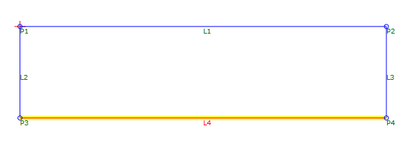
In the example, the L1, L2, and L3 are automatically drawn between points. L4 is manually drawn between P3 and P4.
Note: In this example, because the links create a closed area, a shape can be created.