After you have used the Create View Frames wizard to create view frames, you can create sheets using the Create Sheets wizard.
You can specify whether the sheets are created in the current drawing or in one or more new drawings.
Note: If you choose to create sheets that display profile views, the profile views will be created and placed in the drawing automatically in model space in the file containing the sheets.
- Before you can use the Create Sheets wizard, create a view frame group using the Create View Frames wizard.
- Click
 Find.
Note: On any page of this wizard, you can click to create the sheets using the default choices on the wizard pages. If a criteria that is needed that has not been supplied, then the Create Sheets button is not available (grayed out). You can also click the links on the left side of the wizard to go directly to a wizard page.
Find.
Note: On any page of this wizard, you can click to create the sheets using the default choices on the wizard pages. If a criteria that is needed that has not been supplied, then the Create Sheets button is not available (grayed out). You can also click the links on the left side of the wizard to go directly to a wizard page. - On the
View Frame Group And Layouts page, select a view frame group from the list.
Note: As a reminder, the sheet type that was selected for this view frame group is displayed beneath the View Frame Group list.
- For View Frame Range, all view frames are selected for processing by default, but you can choose a single view frame, or multiple view frames from the group by clicking Selection and then clicking the button.
- In the Layout Creation section, choose how the layouts will be created. A conceptual image on the right side of the wizard page provides an indication of the result.
Option Description (1) 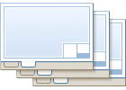
This option may be an appropriate choice if you plan to have several people working on individual sheets. When this option is selected, and you enter 1 for the value, one new layout (sheet) is created in each new drawing. The total number of sheets and drawings depends on the length of the alignment selected and other criteria, such as the size of the viewports in the referenced template. (>1) 
If you choose this option and enter a value greater than 1 (3, for example), then 3 new layouts are created in each new drawing. The total number of sheets and drawings depends on the length of the alignment selected and other criteria, such as the size of the viewports in the referenced template. 
This option may be an appropriate choice if having each individual layout in a separate drawing is not necessary for you, and if you have less than 10 sheets. You may place all the layouts in one newly created drawing. The total number of sheets depends on the length of the alignment selected and other criteria, such as the size of the viewports in the referenced template. For optimal results, it is recommended that you create no more than 10 sheets per drawing. Therefore, this option may not be the best choice if you have more than 10 sheets. If you are generating less than 10 sheets, you may want to generate the layouts in the current drawing. The total number of sheets depends on the length of the alignment selected and other criteria, such as the size of the viewports in the referenced template. Note: For optimal results, it is recommended that you create no more than 10 sheets per drawing. Therefore, this option may not be the best choice if you have more than 10 sheets. - Specify a name for the layouts or accept the default naming template.
- Optionally, you can use the option to automatically align a north arrow block in the sheet(s). Any blocks that exist in the referenced template (.dwt) are displayed in the drop-down list. If no blocks exist in the referenced template, the list displays None. If you select a block from this list, that block will be aligned to the north on the sheet(s).
- Click Next to display the Sheet Set page.
- On the Sheet Set page, in the Sheet Set section, select either New Sheet Set or Add To Existing Sheet Set.
- In the Sheet Set Storage Location field, specify a location where the sheet set file (.dst) will be stored.
- Click
 to browse to a physical drive to store the sheet set.
- If you are logged in to a project in Vault, click
 to browse to a vault location to store the sheet set.
- Click
- In the Sheets section, specify a storage location and name for the sheet file(s) that will be created during this wizard session. If you have chosen to save all sheets in the current drawing (the All Layouts In The Current Drawing choice on the Create Sheets wizard View Frame Group and Layouts page), these fields are not available (read only, grayed out).
- Sheet Files Storage Location: Specifies the location where the sheet files created during this session will be located. Click
to browse to a physical drive to store the sheet set. If you are logged in to a project in Vault, click
to browse to a vault location to store the sheet set.
- Sheet File Name: Specifies the name of the sheet file(s) that will be created.
- Sheet Files Storage Location: Specifies the location where the sheet files created during this session will be located. Click
- Click Next to display the next page in the wizard sequence. If the view frames do not include any profile views, then the Profile Views page of the Create Sheets wizard is not available, and the Data References page is displayed next.
- On the
Profile Views page, you can specify additional settings for profile views. Note that the profile view style and the band set that were selected during view frame creation cannot be changed at this stage; however, the current profile view style and band set that will be used are displayed as read-only on this page. Only additional settings relating to profile views (Other Profile View Options) can be changed at this part of the process. For more information, see
About Profile View Options for Plan Production.
Note: If you need to change these profile view or band set style settings, you must cancel out of the Create Sheets wizard and recreate the view frames, using the updated style choices for the profile views and/or the band sets.
- In the Other Profile View Options section, you can get other settings from an existing profile view, or you can choose settings by launching the Profile View wizard at this point (from this page of the Create Sheets wizard). If you choose to launch the Profile View wizard from the Create Sheets wizard, you will be returned to the Profile Views page of the Create Sheets wizard when you are finished selecting profile view options.
- If you are creating plan and profile sheets, you can choose how to align the data that is displayed in the plan and profile views using the
Align Views options. If you are creating plan only or profile only sheets, these options are not available. These options are useful on projects that require the data displayed in sheets to be aligned according to certain project requirements (such as aligned left, center, or right).
- Align Profile And Plan View At Start: When this option is selected, the left side (start station) match line in the plan view aligns with the left side (start) of the profile view.
- Align Profile And Plan View At Center: When this option is selected, the center of the plan view aligns with the center point of the profile view.
- Align Profile And Plan View At End: When this option is selected, the right side (end station) match line in the plan view aligns with the right side (end) of the profile view.
- Click
Next to display the Data References page.
Note: The Data References page is not available if you chose All Layouts In The Current Drawing in the Layout Creation section of the View Frame Group and Layout page.
- On the Data References page, you can select or omit the data you want to be included in your sheets. Select the check box next to the data references you want displayed in the sheets. Some references cannot be removed from the selection, such as the alignment and profile associated with these sheets. If you are including pipe networks in the destination drawing(s), you may want to check the Copy Pipe Network Labels To Destination Drawings to also copy the labels associated with any selected pipe networks.
- Click Create Sheets to create the sheets.
- If you selected to create sheets containing profile views, you are prompted to select an insertion point in model space to create the profile views. Click a location in the drawing (model space) to insert the profile views.
Note: You will only see profile views in the current drawing if you selected the All Layouts in the Current Drawing option in the Layout Creation section of the View Frame Group and Layout page.
Depending on your Event Manager settings, Event Manager messages may inform you of the location of the sheet sets, as well as the number of layouts created.
Once the sheets are created, the Sheet Set Manager is displayed automatically, showing the newly created sheets in a sheet set. For more information about the Sheet Set Manager, see the Sheet Set Manager Help topics in the AutoCAD Help.