The view frames that are created represent rectangular areas along the alignment that will be displayed on plan/profile or plan-only sheets.

Before you create view frames, the desired alignment must already exist in your drawing. Depending on the type of sheets you want to produce (plan and profile or profile only), you may also need to have a profile already created. If you are creating a plan only view frame (or sheet set), then you do not need to have a profile in the drawing.
- Click
 Find.
Find.
The Create View Frames wizard is displayed.
Note: On any page of this wizard, you can click to create the view frames using the default choices on the wizard pages. If a criteria is needed that has not been supplied, then the Create View Frames button is unavailable (grayed out). You can also click the links on the left side of the wizard to go directly to a wizard page. - On the Alignment page, select an alignment.
- On the
Station Range section, choose one of the following:
- Automatic: Selects the entire alignment. So the start station is the start station of the alignment, and the end station is the end station of the alignment.
- User Specified: When this is selected, you may enter a value or click
 to specify a start and end location (stations) along the alignment in the drawing area.
- Click Next to display the Sheets page.
- On the
Sheets page, in the
Sheet Settings section, under
Choose The Sheet Type You Want To Generate, select one of the following:
In the Template For Plan And Profile Sheet field, click
Option Result (Conceptual Image) Plan And Profile 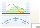
The sheets that will be created will contain plan views and profile views.
Plan(s) Only 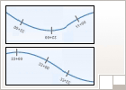
The sheets that will be created will contain plan views only (no profile views).
Profile(s) Only 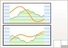
The sheets that will be created will contain profile views only (no plan views).
 to open the Select Layout As Sheet Template dialog box and browse to the template to use for the sheets that will be created. The template you select must have viewports defined as plan and/or profile, depending on the sheet type selected in this dialog box (Plan And Profile,
Plan(s) Only, or Profile(s) Only).
to open the Select Layout As Sheet Template dialog box and browse to the template to use for the sheets that will be created. The template you select must have viewports defined as plan and/or profile, depending on the sheet type selected in this dialog box (Plan And Profile,
Plan(s) Only, or Profile(s) Only).
The plan production templates that are located in the Template folder have viewports that are already configured to the appropriate viewport type: plan, profile, or section. These templates are located in \Users\<user name>\AppData\Local\Autodesk\C3D <version>\enu\Template\Plan Production.
- Click OK in the Select Layout As Sheet Template dialog box.
Note: If you select a template that does not have appropriately defined viewports for the sheet type you select (Plan And Profile, Plan(s) Only, or Profile(s) Only), Autodesk Civil 3D detects this and displays a warning message.
- In the
View Frame Placement section, select one of the following or accept the default:
Option Result (Conceptual Image) Along Alignment 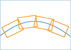
The view frames will be aligned along the alignment. Typically, this is the preferred method for making the most efficient use of paper when plotting.
Rotate To North 
The view frames will be rotated according to the north arrow orientation of the drawing.
- Optionally, you may select the check box next to the Set The First View Frame Before The Start Of The Alignment option, and then enter a value in the value field.
This sets the distance before the start station of the alignment that the first view frame is placed. Entering a distance here provides the specified amount of space before the selected alignment start so that the alignment start does not coincide with the edge of the viewport. If this check box is not selected, then this field is ignored, and the first view frame may be placed at the start of the alignment. Often the view frame start will be as desired without altering this option.
- Click Next to display the View Frame Group page.
- On the View Frame Group page, specify a name, and optionally, a description of the view frame group object that will be created using this wizard.
- On the View Frame section, specify a layer, name, style, and label style for the view frames.
- In the Label Location field, choose the desired location to place the view frame labels. For example, choosing Top Left places the view frame labels at the top left side of the view frame.
- Click Next to display the Match Lines page.
- On the
Match Lines page, if you chose Plan Only, you can choose to insert match lines on the view frames by selecting the check box next to Insert Match Lines. Match lines are only displayed in model space and in plan views. They are not displayed in profile views.
Note: If you do not want match lines included on the plan only view frames, clear the check mark from this option. This disables the options on this page. If you selected to create plan and profile or profile only sheets, this check box is automatically selected, and you cannot edit it (not available, grayed out).
- In the
Positioning section, you may select one or both of the following options, and enter desired values in the text fields. Both these options let you adjust where match lines are placed, and how they may be moved after creation, so that they do not obstruct important drawing data.
- Snap Station Value Down To The Nearest: When this check box is not selected (cleared), match line positioning on the view frame is determined by using a rounding value based on derived stations. When this check box is selected, the match lines are positioned on the view frames based on the rounding calculation value entered. The rounding calculation always rounds down. For example, if the calculated station for a match line is 48+37.69, then a rounding of 100 would place the match line on 48+00.
When Snap Station Value Down To The Nearest is set to ... the station will round to 100 18+00 50 18+50 10 18+60 1 18+65 27+45.3 to 50 27+00 to the next lowest multiple of 50 Note: This option will not accept values that cause the match lines to be placed in undesirable locations, such as before the previous match line or before the beginning of the alignment. If a rounding calculation would result in the match line being placed in an undesirable location, then the rounding calculation is ignored and the match lines are placed at calculated station. - Allow Additional Distance For Repositioning (Increases View Overlap): Because the location of match lines is calculated automatically, it is possible that after you might need to move the match line slightly. For example, in some cases match lines or match line labels may be obscuring data of interest. You can use this option to increase the margin by which you can move (reposition) match lines. Using this option will have a side-effect of increasing the overlap area of view frames. When this check box is selected, you can move the match lines in plan view by the distance specified with this option. This ensures that the match line remains within (between) the intersection of the two neighboring view frames. You should enable this option if you want to be able to move the match lines by a certain distance. Note that having this option enabled is useful if you need to force an overlap of view frames when, on a straight line alignment, adjacent edges or sides of two view frames are at the same location, thereby not allowing enough room for labels.
- Snap Station Value Down To The Nearest: When this check box is not selected (cleared), match line positioning on the view frame is determined by using a rounding value based on derived stations. When this check box is selected, the match lines are positioned on the view frames based on the rounding calculation value entered. The rounding calculation always rounds down. For example, if the calculated station for a match line is 48+37.69, then a rounding of 100 would place the match line on 48+00.
- In the Match Line section, specify a layer, name, and style for the match lines that will be created.
- In the Labels section, specify the labeling criteria for the match line labels, including location.
- Click
Next to display the Profile Views page.
Note: The Profile Views page is not available (grayed out) if a sheet type of Plan Only was chosen on the Sheet Set page of this wizard.
- On the
Profile Views page, verify that an appropriate profile view style and band set have been selected. If desired, you may select a different profile view style and band set.
Note: It is important to note that the profile view style and band set that is used during the Create View Frames wizard are used to calculate the placement of view frames. These styles cannot be changed later for the view frame group.
- Click Create View Frames to create the view frames.
When the wizard has completed creating the view frames, you will notice the following:
- The view frames and match lines are created in the drawing.
- In the Prospector tree, the following objects are created: one view frame group, one or more view frames in a view frames collection, one or more match lines in a match lines collection.
Now that the view frames are created, you may want to adjust the location or labels of the view frames and match lines.
After you are satisfied with how your view frames and match lines are positioned, the next step is to create the sheets using the Create Sheets wizard.