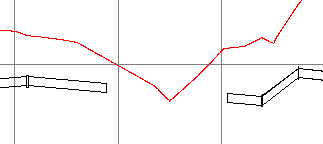
In profile view, you can add pipes and bends, as well as individual pipes, bends, and appurtenances to part-based pressure networks.
- Select a part-based pressure network. The Pressure Networks contextual ribbon tab is displayed.
- On the
Modify panel, click
Edit Network
 Profile Layout Tools
Find.
Profile Layout Tools
Find.
- Use the
Break Pipe command and/or the
Delete Part command to remove the section of the pressure network that you want to replace.
 Important: When deleting parts in profile view, it is important to use the Delete Part command on the ribbon. If you use the AutoCAD Erase command, or the Delete key on the keyboard, the part is only removed from the profile and not from the model. When you attempt to add new parts to the profile view, you may then receive the message "A new part cannot be added because it will overlap an existing part." If you receive this message, examine the pressure network in plan view to see if the parts are actually deleted.
 - Ensure that the start point of the gap is a pipe.
Note: When using the Pipes & Bends option in profile view, you must start adding the parts from an existing pipe. If you begin the command and select a fitting or appurtenance, you will be prompted to first add a pipe. You can do so with the Add Pressure Pipe command.
- Click Pipes & Bends.
- Select the start and end parts of the range in the profile view (the part you want to start drawing from and the part to connect to).
Note: If the parts are found to be co-directional, the command continues. If it is detected that these parts are not co-directional, and may not connect together correctly in plan view, an alert message is displayed suggesting that the design be edited in plan view first in order to establish the correct network path.
- Select the start point for the new bend and pipe.
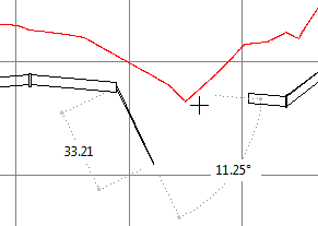
Temporary graphics are displayed as guides. Dashed lines are shown to indicate the length of the pipe and the available bend angles. In the following illustration (which shows an exaggerated profile view), the 11.25 degree bend is snapped to.
- Click to insert the bend and pipe.