Slope patterns are slope indicator lines. They have one or more repeating lines that are aligned with the flow direction. The lines can be the length of the slope or less. They can have a predefined symbol or an AutoCAD block inserted at one end.
Slope patterns are applied between any two feature lines (typically, between a grading footprint and daylight line).
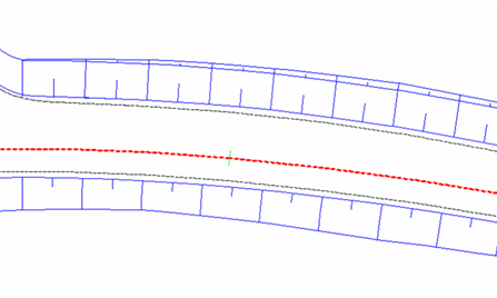
Typical slope pattern usage along a corridor:
To apply a corridor slope pattern
- In
Toolspace, on the
Prospector tab, expand
 Corridors, right-click the corridor, and click
.
Corridors, right-click the corridor, and click
.
- In Corridor Properties dialog box, click the Slope Patterns tab.
- Click Add Slope Pattern >>.
- In the drawing, select the first corridor feature line that will form one side of the slope. If you make an ambiguous selection, the Select A Feature Line dialog box is displayed. Select a feature line from the list.
- Select the second corridor feature line that will form the other side of the slope. If you make an ambiguous selection, the Select A Feature Line dialog box is displayed. Select a feature line from the list.
- Click Apply.
To edit a corridor slope pattern
- In
Toolspace, on the
Prospector tab, expand
Corridors. Right-click the corridor. Click
.
- In the Corridor Properties dialog box, click the Slope Patterns tab.
- To change the slope pattern style, click
 in the
Slope Pattern Style field. Select a style from the
Pick Style dialog box or use the standard style creation tools to edit or create a style.
in the
Slope Pattern Style field. Select a style from the
Pick Style dialog box or use the standard style creation tools to edit or create a style.
- To change either the start or end points for the slope pattern, select either the
Station Start or
Station End fields. Enter the values, or click
 and click the location in the drawing.
- Click Apply.