When contour data is added to a TIN surface, the resulting surface can contain flat spots (triangles whose points all come from the same contour) and flat edges (triangle edges that join points from the same contour or from different contours at the same elevation).
The following illustration shows a surface with flat areas where the triangles (in cyan) of a surface are created from red contour lines. Some of the flat triangles and flat edges are indicated:
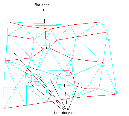
These flat areas represent inaccuracies in the surface. When the contours of such a surface are displayed, they might not match the original contour data around the flat areas. Also, displayed contours might contain points with three contour segments emanating from them instead of the expected two segments. Use the Minimize Flat Areas operation to find and eliminate triangles that have three points at the same elevation and edges that connect points on different data contours at the same elevation.
This command reduces the number of flat areas that result from the addition of contour data to a surface. It helps create a better surface model that realistically reflects a real-world surface.
The Minimize Flat Areas operation finds flat areas defined by triangle edges that are created from either a breakline or a contour. If a surface created from point data contains a flat area defined by three points with the same elevation, the operation does not affect the surface.
You can specify the Minimize Flat Areas By options when using the Minimize Flat Areas operation or during the Add Contour Data operation.
With one exception, the following Minimize Flat Areas options work only for TIN surfaces generated from contour data. In some cases, the Swapping Edges option can change the appearance of the contours displayed on a surface that is not generated from contour data.
Filling Gaps
This option fills the small gaps that sometimes occur in displayed contours and creates one continuous contour. If the two ends of the gap are close enough to be connected by a single triangle edge, the gap is filled by making that edge and the two data contours it joins into a single data contour. No additional points or edges are added.
If you want to control which gaps are filled, you can add contour data without selecting this option, and then use the Check for Contour Problems operation, which reports both ends of the gap. If, after reviewing the results of the operation, you identify gaps that you do not want filled, add a surface point between the two gap endpoints with an elevation above or below the contour. Then use the Minimize Flat Areas operation with the Filling Gaps In Contour Data option selected to fill the remaining gaps.
Swapping Edges
This option scans the surface looking for a flat triangle that shares a non-contour edge with a non-flat triangle. If the two triangles form a convex quadrilateral, the common edge is swapped, creating two non-flat triangles. This may result in other flat triangles sharing non-contour edges with non-flat triangles, and these edges are swapped if possible. The process continues until no more swapping is possible.
This command reverses the direction of a TIN line between four adjacent surface points. To perform this operation, ensure that the surface style has points visibility enabled.
For more information, see About Surface Styles and Visualization.
After the command is performed, the surface size remains unchanged and the surface contains the same number of points and triangles.
Adding Points to Flat Triangle Edges
Like the previous option, this option scans the surface looking for a flat triangle that has all its points on data contours and shares a non-contour edge with a non-flat neighbor. However, instead of swapping the common edge of the triangle pair, a new point is added at the midpoint of the common edge. The elevation of the point is computed using Natural Neighbor Interpolation.
In many cases, this triangle falls at the edge of a chain of triangles that cross the flat area. Once you add the new point, the chain of flat triangles is traversed, with new points being added to flat triangle edges until the end of the chain is reached. The elevations of the points added along the chain are linearly interpolated between the elevations of the starting point and the ending point of the chain.
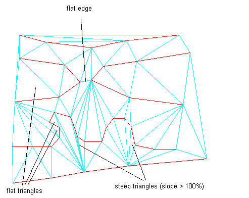
This option results in the removal of more flat triangles than the Swapping Edges option. Any triangle that would be removed by the Swapping Edges option is also removed by this option. This option also generally results in fewer steep triangles. However, additional points and triangles are added to the surface:

In this illustration, 27 points are added to the surface. Most flat triangles are removed, except for some along the top and upper left borders.
Adding Points to Flat Edges
This option addresses flat edges, which are edges that bridge two same-elevation data contours but are not in flat triangles. The surface is scanned for any flat edges with both endpoints on data contours. If the opposing points of the two triangles containing such an edge are both at a higher elevation than the edge, or both at a lower elevation than the edge, then a new point is added at the midpoint of the flat edge. The elevation of the new point is computed using Natural Neighbor Interpolation. Because new points and edges are added, this option increases the size of the surface.
The following illustration shows the same surface after applying both the Adding Points To Flat Triangle Edges and the Adding Points To Flat Edges options. A total of 28 points are added in this example.

One benefit of the Swapping Edges option is that it does not increase the size of the surface. The Adding Points To Flat Triangle Edges and Adding Points To Flat Edges options generally produce better results, but they increase the size of the surface.
Before using the Minimize Flat Areas operation on a surface, you might find it helpful to evaluate flat areas so you can control the results of the operation, as shown in the following examples.
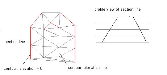
The following illustration shows a surface generated for a ridge where an open contour ends near the border of the surface but not on the border. The contours were added to the surface model with no Minimize Flat Areas. By options specified:
If you run the Minimize Flat Areas operation with the Adding Points to Flat Triangle Edges option, the following results are obtained:
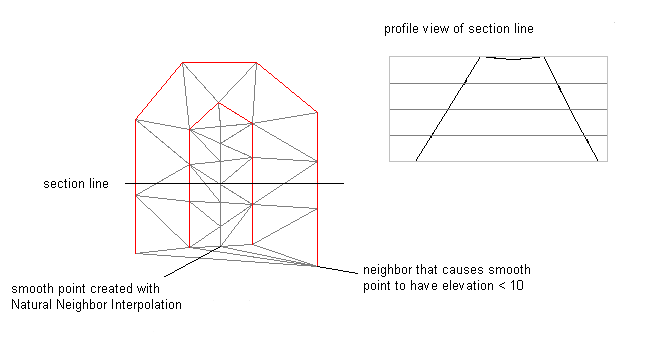
These results occur because the NNI interpolation uses surrounding points to determine an appropriate elevation for a new point. Because all surrounding elevations are lower than the flat triangle, elevations lower than the flat triangle are selected for the added points, resulting in the dip in the ridge.
In this instance, you can supplement the contour data by adding a spot elevation point near the open end of the contour, as shown in the following illustration. Then, the Minimize Flat Areas operation generates a crown as desired.
