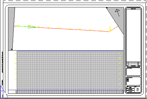
If you select the Insert Match Lines check box on the Match Lines page of the Create View Frames wizard, a match line is created at each view frame intersection.
The first and last view frames in a group have only one match line.
Use the options on the Match Lines page of the Create View Frames wizard to control how match lines are positioned on alignments, to specify a match line style and a match line label style, and to specify by how much distance match lines can be repositioned after you create them. You can set defaults for their styles using the Match Line settings available on the Settings tab in Toolspace.
Like other Autodesk Civil 3D objects, you can edit certain properties of a match line. For example, you can change a match line’s object name, description, object style, or the layer on which it is displayed. Match line objects are displayed in the Prospector tree, and you can control their default style and labeling in the Match Line collection in the Settings tree.
You can edit a match line length using grips, or move match lines. The only way match lines can be deleted is to delete the view frame, or the view frame group, it belongs to. Use the match line style to hide the visibility of match lines if you do not want them to be displayed.
Match lines persist in a drawing as objects with the name AeccMatchLine.
Match Line Style
Use the match line style to control the appearance of the match line. You can set typical style characteristics, such as visibility, layer, color, linetype, linetype scale, and lineweight.
Match Line Mask Area
Match lines have a match line mask area on the outside of each match line. Use the match line mask area to hide or mask the area that exists between the outside of a match line and the inside border or boundary of the view frame. This component exists only in plan views, not profile views, and only in paper space. The following illustration shows an example of the two match line mask areas in gray, on the left and right sides of a plan view viewport:

The Display tab of the Match Line Style dialog box includes an option to specify a hatch pattern for this match line mask area.
Match lines and the match line mask area are displayed only in plan views, not in profile views. The match line mask area exists only in paper space.
Match Line Label Style and Location
Match line labels are displayed on top of the match line mask area, and are therefore visible over it.
You can specify a label style for the label that will be displayed on the left side of a match line or on the right side of a match line. Since each individual match line is displayed in two sheets, it’s convenient to have the ability to set label styles differently for the label that will be displayed on the left side of the match line, and another label style for the label that will be displayed on the right side of the match line.
Also, you can display only one match line label (on the left or on the right side of the match line) by simply turning off the visibility of one match line label.
You can choose to place the left and right side match line labels at the start, end, or middle of the match line, or where the alignment intersects the match line.
Set the defaults for this match line label behavior using the View Frame Group Settings dialog box.