How to configure components and sketches to support slice views.
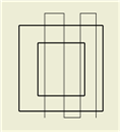
You can show portions of a Drawing View as a slice, or zero-depth section. For example, in a drawing, you may want to show the slice of your customer's product, or vice-versa. The cut profile, or slice line geometry, consists of associated sketch geometry in the selected source view. The Slice operation is performed in a selected target view.
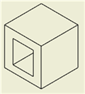
Setting Components to Participate in the Slice Operation
The Slice command also has an option to override the attribute setting of each component in the target view, and perform the Slice operation on all components.
Requirements for Sketch that Defines the Slice Operation
- Must contain at least one open profile (only open profiles are used for the Slice sketch geometry).
- Can be located in a Parent, Child, or Sibling View of the Target View.
- Cannot be entirely made of reference geometry. Reference geometry cannot be selected for Slice sketch geometry.
- Cannot be an unconsumed Model Sketch that is recovered in the Drawing.
- Cannot be created in a Draft View.
Enable Components to Participate in Slice Operation
Use the Section Participation flyout in the browser component context menu, to enable the parts or assembly to participate in the Slice operation.
Assembly and Presentation views support Section Participation flyout. Part views can automatically be sectioned or sliced and do not require this setting.
The Document Settings for each part control the default settings for the Section Participation flyout. The Participate in Assembly and Drawing Sections check box, on the Modeling tab of the Document Settings dialog box, determines whether the part participates in section views. There is no default setting for Slice participation.
- Expand the Target view icon in the browser.
- Under the expanded Target view, right-click the parts or assembly you want to participate in the Slice operation.
- In the context menu, select the Section Participation flyout, and check Slice.
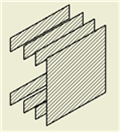
Create a Slice Operation Defined by Sketch Geometry
- Select an existing view for the Source view.
- On the ribbon, click
Place Views tab
 Sketch panel
Create Sketch to open a drawing sketch associated with the view.
Sketch panel
Create Sketch to open a drawing sketch associated with the view.
- Create sketch geometry to define an open slice sketch, and then exit the sketch environment.
- On the ribbon, click Place Views tab Modify panel Slice.
- Select another view for the Target view.
- In the Slice dialog box, select the previously defined Slice sketch as the cut sketch.
- (Optional - Inventor) Check Slice All parts to override Browser component settings and slice all parts in the view, according to the Slice sketch geometry. (Components that are not crossed by the Slice Line do not participate in the Slice operation.)
- Select the previously defined Slice sketch as the cut sketch.
Control the Cut Inheritance for Child Views
The Slice option in the Cut Inheritance section of the Drawing View dialog Display Options tab specifies that child views inherit the slice cut.
- In the graphic window or the browser, select the child view.
- Right-click and select Edit View from the menu.
- On the Display Options tab of the Drawing View dialog box, select the Slice check box in the Cut Inheritance section.