3D Orthogonal Route displays as soon as you begin selecting route points in the graphics window. It contains several elements that guide selection of valid route points.
When the 3D Orthogonal Route first appears, only the line extender displays. With the line extender, you can select points that are offset from a selected edge. After you select a point along the line, other elements of 3D Orthogonal Route appear at the selected point.
The elements that display are based on what is selected, the connection geometry, and set styles. For example, 3D Orthogonal Route displays different elements depending on whether you are creating a pipe route with fittings or a tube route with bends. Some elements are common to both styles.
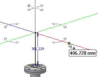
Points that are valid make a connection of the allowable length. They highlight with a green dot as you move the cursor over the lines in the 3D Orthogonal Route display. Points that do not fall within the range set by the style criteria display as a yellow x. If the line is not long enough, you can increase the size of the display.
| For more information | |
|---|---|
| Help topics | |