The various techniques and approaches that are available to model parts and create assemblies can affect performance. Your modeling approach determines the number of occurrences, complexity of geometry, constraint methods, and assembly creation.
It is common to mix techniques to fit your products and design intent. For example, you can use top down modeling to design and build a frame, and then use bottom up modeling to place and constrain components from a library. The following diagrams and brief descriptions provide modeling concepts leaving room for you to experiment with variations of the concept to realize the greatest benefit for your needs.
Legacy Data
- If you use Autodesk Vault, review Vault documentation for information about migrating databases.
- About Migrating with Task Scheduler
- To Migrate Files (Task Scheduler)
- Migration Options Reference
Top-down, Bottom-up, and Middle-out Methods
Top-down
Top Down is a method where you start defining the end result and build in all of the known de-sign criteria. This becomes the base for underlying sub-assemblies and parts. In this way you will have a single conceptual file containing the overall information of the design with a single place for incorporating design changes.
- A much more stable Inventor model
- Faster updates
- More available resources for handling larger data sets
- An easier way of working in a collaborative environment
Skeletal Modeling Methods
No single method suits every design process. You refine your use of the tools to develop efficient processes for producing their designs. Skeletal modeling is an example of that refinement process. Using the tools, customers, like you, have developed approaches to skeletal design that fit their needs. The following methods represent the best practices for using skeletal design methods.
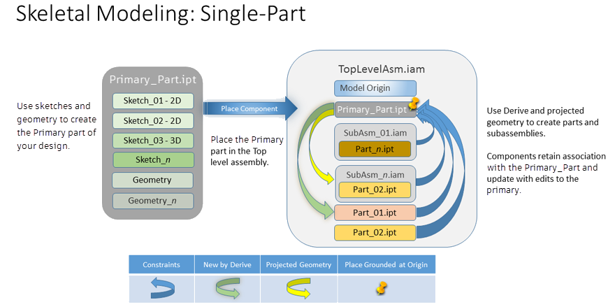
The Single-Level Process uses a single primary part containing sketches and geometry that represents the final design. The primary part is placed in the top-level assembly. All components (parts and subassemblies) are created relative to the primary part. Downstream, modifications to the primary part drive changes in the components associated to the primary part.
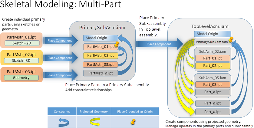
The Multi-Level Process uses individual primary parts comprised of sketches to represent the final assembly. The primary parts are placed and constrained in a primary sub-assembly. The primary sub-assembly is placed in the Top-level assembly. Inside the Top-level assembly, the individual 3D components are modeled using projected geometry from the primary sub-assembly and its primary parts. The 3D components can be contained in logical sub-assemblies or separate, according to the design requirements.
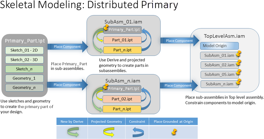
The Distributed Primary uses a single primary part, comprised of sketches and geometry, to define the final assembly. The Primary Part is referenced in the various sub-assemblies and parts as needed. The Primary Part controls the overall layout. The assembly and sub-assemblies are defined or placed with respect to the Primary Part. Each sub-assembly has its own skeleton and drive a portion of the design within itself. Higher level skeletons are used to drive the overall layout or mechanism of the assembly while lower level skeletons can be used to drive the geometry of the parts.
Bottom-up
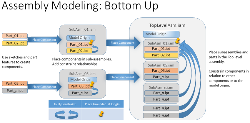
Bottom Up is the traditional way of building assemblies. First, you define the different parts. Then, you put them into sub-assemblies using assembly constraints. The sub-assemblies are then placed into higher lever assemblies up to the top level assembly and in this way, you are working your way from the bottom up. This assembly method results in assemblies with a number of relationships between parts and assemblies.
- It can consume system resources and slow down performance.
- Model changes ripple through the design due to a lot of cross references and/or referenced geometry that are affected.
This diagram is provided as a comparison to the skeletal modeling methods mentioned above.
Middle-out
The Middle out combines aspects of both top-down and bottom-up methods. Some components exist, others are modeled separately or in-context. Cross-part references may be used to drive aspects of the design.
Linking Part Model Parameters
If you share parameters between parts, do not link them by an Excel spreadsheet. When the Excel file changes the software does not distinguish which files are affected, so an update is required for all parts. The performance of large assemblies slows down.
If you use global parameters, those used across designs, establish these parameters in your primary parts and then link them one by one from the Parameters dialog box. This is the 'lightest' reference. Alternatively, use the Derive command in connection with the primary part and select the parameters to use in the derived part. The software detects and updates only those files that a change affected.
For more information: Parameters in models
Managing Component Count
For purchased or standard components consider not placing hardware parts at all, or only place one instead of many. Quantity overrides can be performed on the Bill of Materials and Parts List to accurately capture the required number of fasteners and other hardware in a design. If you need component presence, use component patterns to reduce component count.
You can reduce the number of visible components with the use of View Representations.
Model States
A Model State in a part or assembly stores information about feature and component inclusion. An assembly substitute model state represents an assembly with a single part and can save considerable resources in large assemblies.
To create a new model state: Right-click the Model States folder or an existing model state and select New.
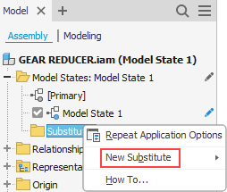
To create a new Substitute model state: Expand the Model States folder, right-click Substitutes, select New Substitute, and then choose Derive Assembly, Simplify, or Select Part File.
Representations
Inventor has two types of representations: View and Position. View can be leveraged to help with large assembly performance.
View Representation
View representations (view reps) store a component's current state when the view is created, edited, and then, saved. The saved view representation preserves component visibility, transparency, sketch visibility, work feature visibility, selection status, and camera state, magnification, viewing angle, and part view representations. View Representations load a component only once. Changing between view representations does not unload or reload components.
Use view representations to control the number components visible at a given time. View representations improve both assembly performance and capacity. Add standard view representations to your templates and configure these for each assembly.
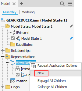
- In the Assembly model browser, expand
Representations and right-click
View and in the context menu, select
New.
- Next, hide or modify components or scene aspects.
Tip: Use the tools in the QAT (Quick Access Toolbar), or in the graphics area, hold "Shift" and right-click to bring up the Selection Filters. To easily select all occurrences of the same component (Select All Occurrences) or all internal parts (Select Internal Components), make use of the appropriate selection option.
- When the content of a view representation matches your intent, Save the document to preserve the representation. If you do not save it, the states will not be preserved.
For more on View Representations see View representations
Simplify Components
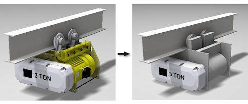
After reducing component counts with model states and view representations, the next thing to do is simplify the model. Simplification is a key step in reducing the number and complexity of components in large assemblies. Purchased parts and company standard parts should be modeled as simply as possible as these are often widely used parts that are modeled once and seldom revised.
Use the Simplify command to simplify an assembly model. Each set of tools provides a different approach to simplification while yielding a simple part that can represent a more complex component.
Simplify and Simplify Substitutes
- Open an Inventor Assembly.
- On the
Assemble tab, in the
Simplification panel, click
Simplify.
Note: At any time in the simplify process you can preview the result by clicking the View Included or View Excluded button in the property panel.
- In the property panel specify the Initial State by selecting the Model State, Design View, and Position View representations pertinent to your assembly.
- Decide whether or not to use Envelopes. If so, expand the group and choose the appropriate option for creating the envelopes.
- In the
Components group, specify the components (parts or assemblies) you want to exclude from the simplified result.
- Select the
 parts or
 assemblies to remove. Use the
 All Occurrence option to quickly eliminate all the selected parts or assemblies.
- Or Remove parts by size. You can select a part and use the bounding box diagonal as input for the size value.
- Use ViewInclude or Exclude to view and select components.
- Select the
- In the Features group, further simplify the components by eliminating non-essential details such small holes, pockets, fillets, and chamfers. You have the option to preserve specific features such as mounting holes and so on.
- in the Output group, specify the output Type, template to use, file name and location, style and other settings.
- Click OK. The part is created and opened in a new window, but has not had an initial save. Make any further refinements and Save the part.
Use the simplified component in an assembly to reduce component count and complexity. If you produce building components and are interested in BIM related simplification processes, use the RVT output option for a simplified Revit format part. To use the output as a Revit family see About Preparing an Inventor Assembly as BIM Content and Inventor to Revit Family File (RFA) Workflow.
Simplify Substitutes uses a similar workflow to create a simplified model, and then associates that result with the source assembly as a Model State, a lightweight representation or substitute for the parent assembly.
For more on Simplify Substitutes see Create a Simplify Substitute.
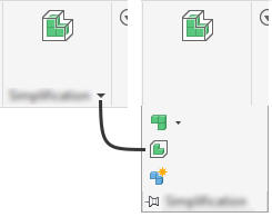
Tools to Simplify View Representations
Simplification tools help reduce complex components to simple shapes that you create using either rectangles or cylinders. The Simplification tools are accessed by clicking the down arrow in the ribbon Simplification panel.
- Create and edit a simplified view representation
- Define rectangular and cylindrical envelopes to substitute for complex components
- Create a simplified part from the representation
Additional Practices to Employ
Assembly Joint and Constraint Relationships
Fully constrain components or ground components that are not designed to move in your assembly. Assembly constraints require the software to perform a calculation. When there are many components in an assembly and each component has multiple assembly constraints, these calculation times can become significant.
- Avoid redundant constraints. For assistance in locating these, use the
Application Options
 Assembly tab
Enable constraint redundancy analysis. Remove redundant constraints, then turn off the option.
Assembly tab
Enable constraint redundancy analysis. Remove redundant constraints, then turn off the option.
- Use a common constraint reference if possible.
- Constrain symmetrical assemblies to the mid-planes or center axes.
- Resolve relationship errors as they occur.
Resolve Relationship errors
It is a good practice to resolve all relationship errors as they occur. However, attempting to resolve all constraint errors through in-place editing, starting at the top level, is an inefficient use of time.
When resolve errors occur a red cross displays in the Quick Access Toolbar (QAT). Clicking that button launches the Design Doctor which reports the errors. In the dialog box, select an error to highlight where the error occurs.
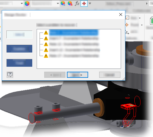
- Open EACH subassembly individually.
- Resolve the relationship problem in the subassembly and save it.
- Open the main or top level assembly, confirm relationship is resolved.
- Repeat these steps as needed.
Model Error Handling
When model features produce errors, these need to be resolved before releasing your designs. Inventor provides Design Doctor (assemblies) and Sketch Doctor (parts) tools to help identify and resolve errors. In particular, missing references and constraint failures are key warnings, and affect Inventor performance. While you can work with missing parts and failed constraints, it is not good practice to do so for extended periods of time. Inventor finds that something is sick, performs an audit, and updates it every time you switch back to that file. If all errors are removed, assemblies behave more predictably and performance improves.
Work Geometry
- After opening the model, in the View tab, in the Visibility panel, click Object Visibility.
- Uncheck All Workfeatures.
- Uncheck other non-essential but visible items, such as weldment symbols if they are not needed in the view.
Turn Off Adaptivity
Adaptivity is a powerful tool for designing parts. Adaptivity should be turned off whenever it is not actively needed because adaptive components are frequently checked for re-computation which in turn affects performance. For assemblies use the Flexible option to exercise the degree of freedom.
- Locate the adaptive part in the assembly browser.
- Right-click the browser node and select Adaptive to remove the checkmark.
Parts
Limit the complexity of purchased or library components to what is needed for accurate design (such as space envelopes, hole sizes, and locations). Adding unnecessary detail (such as textures, threads, coil features, fillets) can affect performance and capacity.
Suppress large feature patterns. Consider using a bitmap texture in place of large feature patterns.
Reduce part complexity. For example, do not model physical threads, fillets, and gear teeth if the detail is not required for manufacturing. Use the Simplification tools to remove complexity.
Engineer's Notebook
The Engineers Notebook is useful for communicating design intent. When you create a note that contains an image, a bitmap embeds into the .ipt or .iam file and increases the file size. The larger the file size, the more hardware resources are used. Therefore, restrict the use of notes with images to minimize file size.
The Engineers Notebook is in its own memory segment and loads only if notes are present. With no notes, the segment does not load, requiring fewer resources.
For more information: Engineers Notebook
Drawings of Large Assemblies
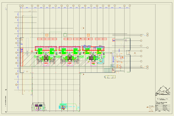
- Enabling background updates of drawing views displays raster drawing views for large assemblies and calculates precise drawing views at the background as you work. You can review the drawing or create drawing annotations before calculating drawing views finishes. See Preferences and Settings for all large assembly related Application Options settings.
- Using design view representations. Components rendered invisible in the design view do not load into memory. Specify a simplified design view representation and model state before opening the model file.
- Close the assembly file used for a drawing view to prevent its graphics from being loaded into memory.
- On the ribbon, click
Place Views tab
Create panel
Base.
Click Open an Existing File
 , and locate and select the assembly file.
- In the File Open dialog box, click Options and then select a design view representation and model state in the File Open Options dialog, and click OK.
- Click Open to return to the Drawing View dialog box.
- Specify the drawing view properties, and if appropriate, place projected views.
- Click OK to close the Drawing view dialog box.
- Using Model State representations. When creating a drawing of a top-level assembly, this removes unneeded components or replaces many parts with a single part representation. As a result, Inventor does not include them when computing the drawing view. Remember to use only one Model State per drawing to avoid introducing performance impact.
- Before starting the Base View command, clicking the Document Tab of the respective model to activate the appropriate document. This avoids calculating the base view preview for a different model. You can also close the last active model document, and select the source document manually.
- Selecting the Suppress option for several drawing views.
- Avoid or reduce the use of property overrides at the edge level. Use feature, body, or component level overrides instead whenever possible.
- Purge unused drawing styles.
- Keep drawing file size as small as possible by:
- Limiting the number of views on a sheet.
- Limiting the number of sheets in the drawing.